background image

Chapter 3 


QDSP-400 Series User’s Manual 


Table 5 Advanced Menu – Super IO Configuration 

BIOS SETUP UTILITY 

M a i n


A d v a n c e d

      P o w e r       B o o t        S e c u r i t y         S a v e   &   E x i t 

Super IO Configuration 




: Select Screen 

↑↓: Select Item 
Enter: Select 
+/-: Change Opt. 
F1: General Help 
F2: Previous Values 
F3: Optimized Defaults 
F4: Save & Reset 
ESC: Exit 


> Serial Port 1 Configuration 


Version 2.18.1263. Copyright (C) 2016 American Megatrends, Inc. 


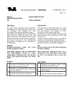
Table 6 Advanced Menu – Super IO Configuration - Serial Port 1 Configuration 

BIOS SETUP UTILITY 

M a i n


A d v a n c e d

      P o w e r       B o o t        S e c u r i t y         S a v e   &   E x i t 

Serial Port 1 Configuration 




: Select Screen 

↑↓: Select Item 
Enter: Select 
+/-: Change Opt. 
F1: General Help 
F2: Previous Values 
F3: Optimized Defaults 
F4: Save & Reset 
ESC: Exit 


Serial Port 

[Enabled] 

Device Settings 

IO=3F8h; IRQ=4; 


Change Setting 

[Auto] 

Serial Port 1 Type 

[RS232] 

Version 2.18.1263. Copyright (C) 2016 American Megatrends, Inc. 


Serial Port 

Options: Disabled, Enabled 

Change Settings 

Options: Auto; 

IO=3F8h; IRQ=4; 

IO=3F8h; IRQ=3, 4, 5, 6, 7, 9, 10, 11, 12; 

IO=2F8h; IRQ=3, 4, 5, 6, 7, 9, 10, 11, 12; 

IO=3E8h; IRQ=3, 4, 5, 6, 7, 9, 10, 11, 12; 

IO=2E8h; IRQ=3, 4, 5, 6, 7, 9, 10, 11, 12; 

Serial Port 1 Type 

Options: RS232, RS422, RS485 


RS485 Duplex Mode      [Half Duplex] 

Options: Half Duplex, Full Duplex 


RS485 Auto Flow Control   [Disabled] 

Options: Disabled, Enabled 


Summary of Contents for QDSP-400 Series

Page 1: ...QDSP 400 Series Mini Digital Signage Player with Intel Skylake Kaby Lake U Series Processors User s Guide...

Page 2: ...packing 7 Regulatory Compliance Statements 7 Maintaining Your Computer 8 Chapter 1 Introduction 11 Overview 11 Product Specifications 12 System tour 13 Mechanical Dimensions 17 Chapter 2 Getting Start...

Page 3: ...le 1 Product Specifications 12 Table 2 BIOS Main Menu 25 Table 3 Advanced Menu 26 Table 4 Advanced Menu Display Configuration 27 Table 5 Advanced Menu Super IO Configuration 28 Table 6 Advanced Menu S...

Page 4: ...Use extreme caution when installing or removing components Refer to the installation instructions in this user s guide for precautions and procedures If you have any questions please contact our Post...

Page 5: ...its connector or on its strain relief loop not on the cable itself Some cables have a connector with locking tabs If you are disconnecting this type of cable press in on the locking tabs before discon...

Page 6: ...Don t touch the components or contacts on a board Hold a board by its edges or by its metal mounting bracket Do not handle or store system boards near strong electrostatic electromagnetic magnetic or...

Page 7: ...pment has been tested and found to comply with limits for a Class B digital device pursuant to Part 15 of the FCC rules These limits are designed to provide reason able protection against harmful inte...

Page 8: ...erheating can cause a variety of problems including premature aging and failure of chips or mechanical failure of devices If the system has been exposed to abnormally cold temperatures allow a two hou...

Page 9: ...ring a system through the AC power cord Surge protectors however do not offer protection against brownouts which occur when the voltage drops more than 20 percent below the normal AC line voltage leve...

Page 10: ...S systems that provide only 5 minutes of battery power let you conduct an orderly shutdown of the system but are not intended to provide continued operation Surge protectors should be used with all UP...

Page 11: ...ovides flexible network connection and peripheral integration In addition it has an IR receiver on front panel and allows users to remotely control the content displayed on connected screens Checklist...

Page 12: ...DC 24 V Phoenix Connector Power Adapter AC to DC 100 V 240 V Firmware BIOS AMI uEFI BIOS w 128 Mb SPI Flash Watchdog Programmable WDT to generate system reset event H W Monitor Input Core Voltages CPU...

Page 13: ...ter with some peripheral acting as additional plug in sites or hubs LINE OUT MIC IN The combo headphone microphone jack 3 5 mm is used to connect the system s audio out signal to amplified speakers or...

Page 14: ...pter 1 QDSP 400 Series User s Manual IR Receiver The IR receiver is an infrared receiving sensor allowing users to remotely control the box PC itself or the content that is displayed on connected scre...

Page 15: ...Power supplied through this jack connector supplies power to the PC To prevent damage to the PC always use the supplied power adapter Kensington Lock Slot The slot is used for attaching a lock and ca...

Page 16: ...r s Manual External Antenna Spared hole on the casing for connecting Wi Fi or 3G 4G external antenna Clear CMOS 1x reset button for clear CMOS External Power Button The external power button allows po...

Page 17: ...Chapter 1 QDSP 400 Series User s Manual Mechanical Dimensions 130 x 111 x 35 mm W x D x H Figure 3 Mechanical Dimensions...

Page 18: ...Chapter 2 QDSP 400 Series User s Manual HDMI DP Chapter 2 Getting Started Setting up your PC Connecting the monitor Connect the HDMI DP cable from your display to the HDMI DP port Figure 4 HDMI DP...

Page 19: ...does not come with a keyboard and mouse but you can use any USB keyboard or mouse with your computer Figure 5 Connecting USB mouse keyboard NOTE Using a third party USB mouse or keyboard may require...

Page 20: ...r 2 QDSP 400 Series User s Manual RJ45 Connecting to a network device Connect one end of a network cable to the LAN port on the system rear panel and the other end to a hub or switch Figure 6 RJ45 con...

Page 21: ...tem 1 Connect the power adapter cable to the DC jack Phoenix connector DC IN of QDSP 400 Series 2 Connect the power cable to the power adapter 3 Connect the power cable to a power outlet 4 Press the p...

Page 22: ...acket and make sure the bracket is hooked with the fins of the system housing NOTE The ventilation slots located near the DC jack are for air outtake and must be placed upwards those located near COM...

Page 23: ...with a Kensington Lock QDSP 400 Series has a Kensington lock slot for the Kensington MicroSaver With the Kensington MicroSaver a sturdy steel cable you can attach your QDSP 400 Series to a stationary...

Page 24: ...ease contact us AMI s ROM BIOS provides a built in Setup program which allows the user to modify the basic system configuration and hardware parameters The modified data will be stored in a battery ba...

Page 25: ...nu BIOS SETUP UTILITY M a i n A d v a n c e d P o w e r B o o t S e c u r i t y S a v e E x i t Product Information Select Screen Select Item Enter Select Change Opt F1 General Help F2 Previous Values...

Page 26: ...e Opt F1 General Help F2 Previous Values F3 Optimized Defaults F4 Save Reset ESC Exit Onboard LAN1 Boot Disabled Audio Controller Enabled Display Configuration Super IO Configuration CPU Configuration...

Page 27: ...Reset ESC Exit Primary Display Auto UMA Frame Buffer Size 256 MB DVMT Pre Allocated 32 MB DVMT Total Gfx Mem 256 MB Primary IGFX Boot Display VBIOS Default Version 2 18 1263 Copyright C 2016 American...

Page 28: ...o w e r B o o t S e c u r i t y S a v e E x i t Serial Port 1 Configuration Select Screen Select Item Enter Select Change Opt F1 General Help F2 Previous Values F3 Optimized Defaults F4 Save Reset ESC...

Page 29: ...alues F3 Optimized Defaults F4 Save Reset ESC Exit EIST Enabled Turbo Mode Enabled Hyper Threading Enabled VT d Enabled Active Processor Cores All Intel VMX Virtualization Technology Disabled Version...

Page 30: ...pt F1 General Help F2 Previous Values F3 Optimized Defaults F4 Save Reset ESC Exit SATA Controller s Enabled SATA Mode Selection AHCI Serial ATA Port 1 Empty Port 1 Enabled mSATA Port 1 Empty Port 1 E...

Page 31: ...Enter Select Change Opt F1 General Help F2 Previous Values F3 Optimized Defaults F4 Save Reset ESC Exit USB Devices 1 Keyboard Legacy USB Support Enabled xHCI Hand off Enabled USB Mass Storage Driver...

Page 32: ...Change Opt F1 General Help F2 Previous Values F3 Optimized Defaults F4 Save Reset ESC Exit Smart FAN Configuration CPU Temperature 51 C Memory Temperature 41 C System Temperature 41 C CPU Fan Speed 42...

Page 33: ...me By LAN Device Disabled Resume By PCI E Device Disabled Resume By Ring Device Disabled Resume By RTC Alarm Disabled WatchDog Timer Configuration Version 2 18 1263 Copyright C 2016 American Megatrend...

Page 34: ...us Values F3 Optimized Defaults F4 Save Reset ESC Exit Full Screen LOGO Display Disabled Setup Prompt Timeout 1 Bootup NumLock State On CSM Support Enabled Boot Option Filter Legacy only Boot Option P...

Page 35: ...r when entering Setup If ONLY the User s password is set then this is a power on password and must be entered to boot or enter Setup In Setup the User will have Administrator rights The password lengt...

Page 36: ...o o t S e c u r i t y S a v e E x i t Save Changes and Reset Discard Changes and Reset Save Options Save Changes Discard Changes Restore Defaults Select Screen Select Item Enter Select Change Opt F1 G...

Page 37: ...IOS asks for a confirmation before exiting Discard Changes Discards changes done so far to any of the setup values This option allows you to discard the selections you made and restore the previously...

Page 38: ...n operating system and the necessary drivers to operate it After you have finished assembling your system and connected the appropriate power source power it up using the power supply and install the...

Reviews: