Chapter 2
16
OPM Series User’s Manual
Getting Started
Setting up your PC
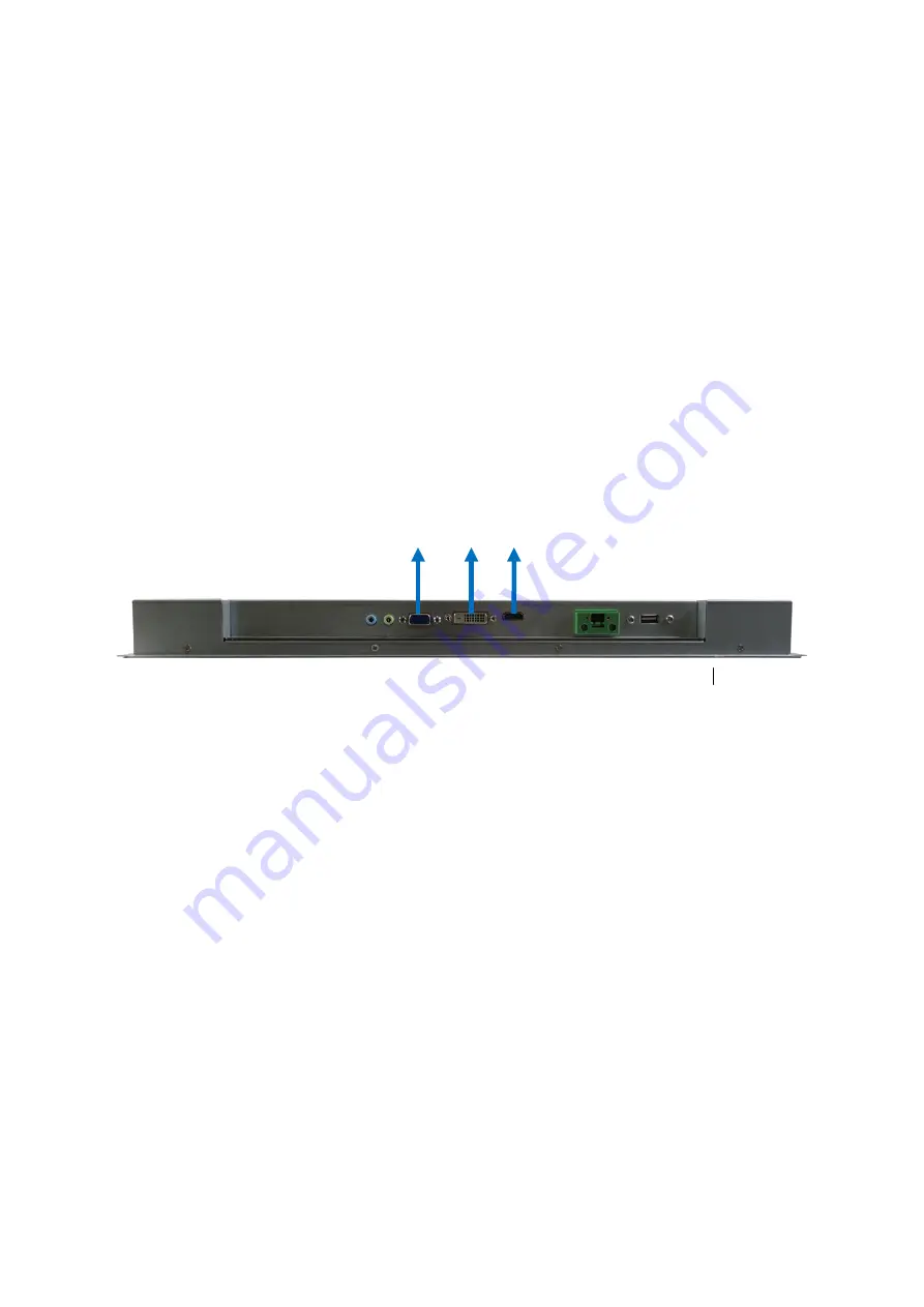
Connecting the monitor
Connect the HDMI / VGA/ DVI-D cable from your display to the HDMI / VGA/ DVI-D
port.
Figure 4 VGA / DVI-D / HDMI
VGA DVI-D HDMI
Page 1: ...OPM Series Open Frame Monitor User s Guide...
Page 2: ...Preface 7 How to Use This Guide 7 Unpacking 7 Regulatory Compliance Statements 7 MaintainingYour Computer 8 Chapter 1 Introduction 10 Overview 10 Product Specifications 1 1 System tour 13 Mechanical...
Page 3: ...VESA Mounting Hole Locations 21 Figure 9 Panel Mount Cut out hole and maximum panel thickness 15 6 Model 22 Figure 10 Panel Mount Cut out hole and maximum panel thickness 18 5 Model 22 Figure 11 Pane...
Page 4: ...allation instructions in this user s guide for precautions and procedures If you have any questions please contact our Post Sales Technical Support Access can only be gained by service persons or by u...
Page 5: ...ned to avoid bending any connector pins Also before connecting a cable make sure both connectors are correctly oriented and aligned CAUTION Do not attempt to service the system yourself except as expl...
Page 6: ...dle or store system boards near strong electrostatic electromagnetic magnetic or radioactive fields Instructions for Lithium Battery WARNING Danger of explosion when battery is replaced with incorrect...
Page 7: ...ment has been tested and found to comply with limits for a Class B digital device pursuant to Part 15 of the FCC rules These limits are designed to provide reason able protection against harmful inter...
Page 8: ...rheating can cause a variety of problems including premature aging and failure of chips or mechanical failure of devices If the system has been exposed to abnormally cold temperatures allow a two hour...
Page 9: ...er source voltage at a fairly constant level and therefore can handle brownouts Because of this added protection line conditioners cost more than surge protectors However line conditioners cannot prot...
Page 10: ...nce It comes with a variety of display ports including 1x HDMI 1x DVI D and 1x VGA for various viewing options and optional 1x USB port for touch functionality Checklist OPM Series User manual CD Quic...
Page 11: ...rear Audio 1x Line in on rear 1x Line out on rear USB 1x USB2 0 Type A on rear for Touch optional Power Connector 2 Pin Phoenix Connector on rear Input Voltage DC 12V default DC 24V optional Button S...
Page 12: ...Chapter 2 12 OPM Series User s Manual Mounting Open Frame Mount VESA Mount Panel Mount Certification CE FCC Class A Table 1 Product Specifications...
Page 13: ...r always use the supplied power adapter HDMI HDMI connector for display input DVI D DVI D is an acronym which means Digital Video Interface Digital Essentially it is a cable that connects two devices...
Page 14: ...Chapter 2 14 OPM Series User s Manual Mechanical Dimensions Dimension 425 1 x 272 6 x 40 0 mm W x H x D Figure 2 Mechanical Dimensions 15 6 Model...
Page 15: ...Chapter 2 15 OPM Series User s Manual Dimension 491 6 x 312 5 x 40 0 mm W x H x D Figure 3 Mechanical Dimensions 18 5 Model...
Page 16: ...6 OPM Series User s Manual Chapter 2 Getting Started Setting up your PC Connecting the monitor Connect the HDMI VGA DVI D cable from your display to the HDMI VGA DVI D port Figure 4 VGA DVI D HDMI VGA...
Page 17: ...em 1 Connect the power adapter cable to the DC IN of the OPM Series 2 Connect the power cable to the power adapter 3 Connect the power cable to a power outlet 4 Press the power button to turn on the m...
Page 18: ...mounting is shown below Front Mount Outside Mount 15 6 Model Step 1 Make a cutout on the fixture eg wall Cutout 397 1 x 244 6 mm Step 2 Insert the monitor into the cutout of the fixture from the fron...
Page 19: ...pectively Figure 6 Open frame mount front mount and cut out hole Rear Mount Inside Mount 15 6 Model Step 1 Make a cutout on the fixture eg wall Cutout 347 16 x 196 59 mm based on active area of the pa...
Page 20: ...12 8 x 234 4 mm based on active area of the panel Step 2 Align the active area of the panel with the cutout of the fixture from the rear side Step 3 Fasten 14 screws from the rear side 4 on top bottom...
Page 21: ...th VESA FDMI 100 standard mounting holes as shown below Use 4 screws with the appropriate length for your mounting bracket Figure 8 VESA Mounting Hole Locations NOTE To fasten the metal shelf your mon...
Page 22: ...ed and comes with brackets and screws for this purpose The required cutout for panel mounting and maximum panel thickness is shown below Figure 9 Panel Mount Cut out hole and maximum panel thickness 1...
Page 23: ...ert a Panel Mount Bracket into each Bracket Opening Step 3 Secure Chassis to Panel by tightening the screws Figure 11 Panel Mounting 15 6 Model Step 1 Remove 8 Bracket Opening Covers from Bracket Open...
Page 24: ...al icon 2 To move to the next setting item 3 To display the next setting option 4 To increase the setting Down 1 To move to the previous functional icon 2 To move to the previous setting item 3 To dis...
Page 25: ...nder that functional icon A cursor will appear in front of one of the setting items in the sub menu when entering the sub menu as shown in the middle figure above Use Up and or Down button to move to...
Page 26: ...n Table 3 Picture Menu Picture Back Light Options 0 100 Brightness Options 0 100 Contrast Options 0 100 Sharpness Options 0 4 Table 4 Image Setting Menu Image Setting Auto Adjust Options N A H Positio...
Page 27: ...ble 5 Color Menu Color Color Temp Options Cool Warm User Color Effect Options Standard Game Movie Photo Vivid User Hue Options 0 100 Saturation Options 0 100 Table 6 Signal Source Menu Signal Source O...
Page 28: ...ptions 0 100 Mute Options Off On Table 8 OSD Menu Menu OSD Menu OSD Timer Options 5 60 OSD H Position Options 0 100 OSD V Position Options 0 100 OSD Transparency Options 0 7 Language Options English F...
Page 29: ...Chapter 3 29 OPM Series User s Manual Table 9 Information Menu Information Options N A...