


MITX-V1K0 Series - User Guide, Rev. 1.0
// 48
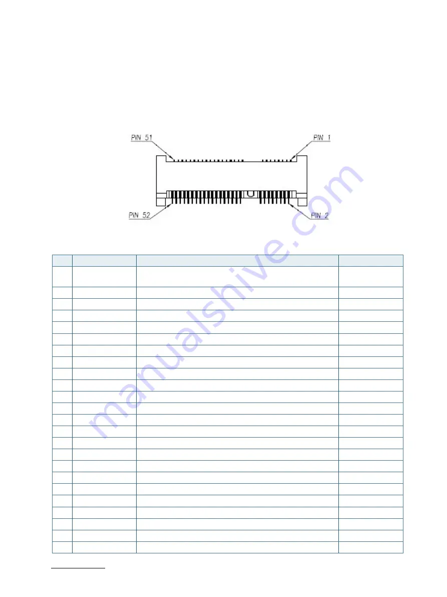
7.14.
mPCIe Socket (MPCIE1)
Full-sized Mini-PCI Express V1.2 socket (MPCIE1). Socket MPCIE1 supports mPCIe, USB 2.0 and SIM-card socket. The
SIM-card socket makes it possible to use a WWAN wireless modem in this mPCIe slot. The USB does support WAKE
function.
Figure 29: mPCIe Slot Connector MPCIE1
Table 36: Pin Assignment MPCIE1
Pin
Signal
Description
Note
1
WAKE#
Requests the host interface to return to full operation and
respond to PCIe
2
+3.3VSB
+3.3 V standby power supply
3
Reserved
4
Ground
5
Reserved
6
+1.5V
+1.5 V power supply
7
CLKREQ#
Reference clock request signal
8
UIM_PWR*
Power source for User Identity Modules (UIM)
9
Ground
10
UIM_DATA*
Data signal for User Identity Modules (UIM)
11
REFCLK-
Reference clock differential pair (-)
12
UIM_CLK*
Clock signal for User Identity Modules (UIM)
13
Reference clock differential pair (+)
14
UIM_RESET*
Reset signal for User Identity Modules (UIM)
15
Ground
16
UIM_VPP*
Variable supply voltage for User Identity Module (UIM)
17
Reserved
18
Ground
19
Reserved
20
W_Disable#
Wireless disable signal
21
Ground
22
PERST#
PCI Express reset
23
PERn0
PCIe Lane 0 receiver differential pair (-)
24
+3.3VSB
+3.3 V standby power supply