background image

Q40 Tape Library 

Installation and Operations Manual


511026 Rev. 07-01-19

 

164 

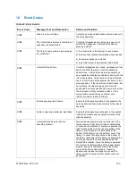
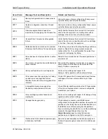
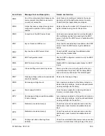
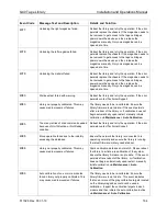
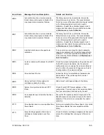
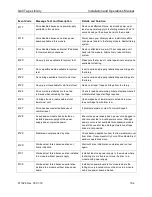
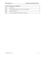
Event Code 

Message Text and Description 

Details and Solution 

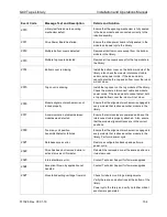
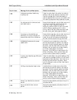
4077 

Unlocking the right magazine failed. 

Reboot the library and retry the operation. If the error 
persists replace the chassis. If the magazine needs to 
be removed to get access to the tape cartridges, 
power down the device and then release the 
magazine manually. Only one magazine can be 
opened at a time. 

4078 

Unlocking the left magazine failed. 

Reboot the library and retry the operation. If the error 
persists replace the chassis. If the magazine needs to 
be removed to get access to the tape cartridges, 
power down the device and then release the 
magazine manually. Only one magazine can be 
opened at a time.


4079 

Unlocking the mailslot failed. 

Reboot the library and retry the operation. If the error 
persists replace the chassis. If the magazine needs to 
be removed to get access to the tape cartridges, 
power down the device and then release the 
magazine manually. Only one magazine can be 
opened at a time.


4080 

Wellness test failed with warning. 

Reboot the library and retry the operation. If the error 
persists contact Technical Support.


4083 

Library not properly calibrated. This may 
cause media movement failures. 

The library needs to be re-calibrated. Ensure the 
library firmware is up to date. If this event persists 
after a reboot of the library, or if calibration does not 
begin automatically upon restart, manually initiate 
calibration via 

Maintenance > Auto Calibration

4085 

Too many retries of drive command needed 
because of Unit Attention or Not Ready 
condition. 

Reboot the library and retry the operation. If the error 
persists contact Technical Support.


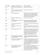
4086 

Move operation failed due to the inability 
accessing the database. 

Ensure the network the library is connected to is 
operating normally and ensure the library is running 
the latest firmware. Library needs reboot. 

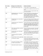
4088 

Library not properly calibrated. This may 
cause media movement failures. 

Some calibration data does not match. Please reboot 
the library to initiate a re-calibration of the system. 
Ensure the library firmware is up to date.  If this event 
persists after a reboot of the library, or if calibration 
does not begin automatically upon restart, manually 
initiate calibration via 

Maintenance > Auto 

Calibration


4089 

Auto calibration of one or more modules 
failed. Library not properly calibrated. This 
may cause media movement failures.  

The library needs to be re-calibrated. Ensure the 
library firmware is up to date.  This event indicates 
that one or more of the gray calibration targets located 
on the library magazines could not be used in 
calibration.  Inspect the calibration targets in each 
module and then initiate the auto-calibration routine 
via 

Maintenance > Auto Calibration

Summary of Contents for Q40

Page 1: ...1 Q40 Tape Library Installation and Operations Manual Document No 511026 Rev 07 01 19...

Page 2: ...the contents of this document and specifically disclaims any implied warranties of merchantability or fitness for any particular purpose Further QUALSTAR reserves the right to revise this publication...

Page 3: ...Qualstar does not affect warranty provided the user strictly adheres to the instructions herein The tape library is physically abused or used in a manner that is inconsistent with the operating instr...

Page 4: ...19 3 1 Planning Installation 19 3 2 Location Requirements 19 3 3 SAS Configuration Requirements 20 3 4 Fibre Channel Configuration Requirements 21 3 5 Planning Module and Rack Layout 22 3 6 Internal I...

Page 5: ...zine Buttons 47 5 3 Operation 48 5 4 Configuration 50 5 5 Maintenance 62 5 6 Status 70 6 Operating the library using the RMI 74 6 1 Using the Library Main Screen with the RMI 74 6 2 Configuring the Li...

Page 6: ...placing a Controller Board 125 7 8 Installing or Replacing a Drive Power Board 127 7 9 Replacing a Module Base or Expansion 129 7 10 Replacing the Robotic Assembly and Spooling Mechanism 133 7 11 Repl...

Page 7: ...511026 Rev 07 01 19 7 This page intentionally left blank...

Page 8: ...ocument uses the reference Q40 to refer to the Q40 Tape Library 1 1 General Warnings Document Conventions WARNING Indicates that failure to follow directions could result in bodily harm or death CAUTI...

Page 9: ...the levelling jacks Install stabilizing feet on the rack Extend only one rack component at a time CAUTION Static Sensitive Risk of damage to devices A discharge of static electricity damages static s...

Page 10: ...ion or operation This product is intended for installation and operation in a computer rack with the front and rear doors closed and secured Only personnel with technical and product safety training s...

Page 11: ...figurations Rackmount Installation All Q40 Libraries start with a Base Module Up to 6 Expansion Modules can be added as needed to support customer requirements The architecture has been designed to su...

Page 12: ...perations Manual 511026 Rev 07 01 19 12 Module Quantity Supported Library Configurations 2 Module Library Base Module 1 Expansion Module 3 Module Library Base Module 2 Expansion Modules 4 Module Libra...

Page 13: ...v 07 01 19 13 Module Quantity Supported Library Configurations 5 Module Library Base Module 4 Expansion Modules 6 Module Library Base Module 5 Expansion Modules 7 Module Library Base Module 6 Expansio...

Page 14: ...brary and within a single module Listed below in Table 2 are the tape drives that have been tested and implemented in the Q40 Table 2 Supported Tape Drives LTO Drives LTO 6 Half Height FC Single Port...

Page 15: ...LED Amber Base Module Only 8 Error LED Amber Base Module Only 9 USB Port Base Module Only 10 Operator Control Panel OCP Display Base Module Only 11 Back Return Button Base Module Only 12 Navigation Bu...

Page 16: ...xpansion Module 3 Half Height Tape Drive Bays 4 Upper Expansion Module Connection Port 5 USB Port Optional on Base Module Only 6 Ethernet Port A Base Module Only 7 Ethernet Port B Optional on Base Mod...

Page 17: ...7 8 HH SAS Dual Port 1 SAS Port A 2 SAS Port B 3 Tape Drive Power LED Green 2 6 LTO 6 7 8 HH FC Single Port 1 FC Port A 2 Tape Drive Power LED Green 2 7 LTO 6 7 8 HH FC Dual Port 1 FC Port A 2 FC Por...

Page 18: ...8 Power Supply Rear Panel LEDs 1 White AC power connected but Module Powered Off 2 Green Module Powered On 2 9 Element Numbering The library will generally display logical element numbering of module...

Page 19: ...le 3 Location Requirements Criteria Definition Rack Requirements Standard 19 inch rack minimum depth of 1 meter with an appropriate of U s Rack Units of clearance for the planned module quantity Rack...

Page 20: ...are shown in the table below Table 4 Supported SAS Speeds LTO Generation Supported Speeds LTO 6 1 5 Gbps 3 Gbps 6 Gbps LTO 7 1 5 Gbps 3 Gbps 6 Gbps LTO 8 1 5 Gbps 3 Gbps 6 Gbps CAUTION High quality SA...

Page 21: ...t Supported speeds by drive generation are listed in the table below Table 5 Supported Fibre Channel Speeds LTO Generation Supported Speeds LTO 6 2 Gbps 4 Gbps 8 Gbps LTO 7 2 Gbps 4 Gbps 8 Gbps LTO 8...

Page 22: ...al IP address range and the external IP addresses it is required to select the internal IP range before the tape library gets connected to the external Ethernet port Therefore a file which contains th...

Page 23: ...eighs more than 20 kg 44 lbs without drives or tapes and more than 35 kg 77 lbs with 3 tape drives and 40 tapes Risk of personal injury Before moving or lifting a library Observe local health and safe...

Page 24: ...operate varies by 15 C 30 F from where the module was stored allow it to acclimate for at least 12 hours prior to unpacking Unpacking a Q40 Base Library or Expansion Module 1 Before opening and removi...

Page 25: ...assistance lift the module out of the bottom foam nest remove the wrapping from the module and then place the module on the work surface CAUTION Do not place a module on either the ends or sides as th...

Page 26: ...hipment by an insertion foam which has to be removed prior to installation 9 To remove the top cover plate from the Base Module unlock the top cover using two small screwdrivers 10 Lift the cover fron...

Page 27: ...essory Kit a One packet of rack mount hardware b Expansion Interconnect Cable For SAS libraries you must provide SAS cabling with the correct configuration for your HBA For Fibre Channel libraries you...

Page 28: ...ge from the pivot point at the unit center 2 Install top cover on the Expansion Module that will be installed on the top of the library a Place the Expansion Module on a work table b With the front of...

Page 29: ...athead screwdriver or Torx screwdriver into the hole and slide sidewards to unlock the spring loaded lock d Lower the front end of the cover and pull gently forward to disengage from the pivot point a...

Page 30: ...ons for any additional module 3U higher To install the rails into the rack starting from the lowest rack location 1 Locate the 4 adapter blocks 4 Philips screws Shipped in the accessory box and 2 rack...

Page 31: ...re installing multiple modules verify that this module has been installed directly above or below its adjacent module and is contained within the correct 3U volume The gap between modules must be less...

Page 32: ...ting with the bottom pair of modules align each module with the module below Repeat for each pair of modules a Move the alignment lever to the locked position If you encounter resistance adjust the po...

Page 33: ...must have drive bay covers installed MECHANICAL HAZARD Danger Risk of hand pinching Keep hands clear during operation 3 15 Connecting Fibre Channel Cables 1 Remove the FC port caps if necessary Attach...

Page 34: ...s confirms the presence of the existing modules and searches for any new modules 3 18 Using the Configuration Wizard Start the Initial Configuration Wizard from the OCP The wizard will guide you throu...

Page 35: ...ed on the barcode media identifier into a tape drive For example the library will not load a cartridge labeled as L3 into an LTO 6 tape drive Your host software may need to keep track of the following...

Page 36: ...dge into the device make sure the write protect switch on the front of the cartridge is in the desired position Slide the switch to the left to allow the device to write data to the cartridge Slide th...

Page 37: ...ta cartridges are pre recorded with a magnetic servo signal This signal is required to use the cartridge with the LTO tape drive Keep magnetically charged objects away from the cartridge To ensure the...

Page 38: ...Incompatible Incompatible LTO 4 Media Unencrypted Incompatible Read Write Read Write Read Only Incompatible Incompatible LTO 4 Media Encrypted Incompatible Read Write with encryption key Read Write wi...

Page 39: ...ocated on the left and right side of each module The LED in the translucent button indicates different states of the mailslot or magazine LED OFF mailslot is not enabled LED steady ON mailslot is enab...

Page 40: ...mailslot will relock after 30 seconds IMPORTANT You can enable mailslots only through the Configuration Mailslots page on the RMI Wait before pulling out the mailslot until the LED is quickly flashing...

Page 41: ...the magazine to the unit 6 Push the magazine handle slowly until the magazine release latch snaps into place The magazine locks into place 7 Repeat steps 1 through 3 for each of the other magazines I...

Page 42: ...library robotic activity Clean Amber when a tape drive is requesting cleaning Attention Amber blinking if the library has detected a condition for which user attention is necessary Error Amber if an...

Page 43: ...intenance or operation functions Administrator The administrator password is required to login as the administrator The default PIN is 0000 The default administrator password is adm001 The administrat...

Page 44: ...ry first power up of the library the user is prompted to walk through the Initial Configuration Wizard It is recommended to walk completely through the wizard and finish the wizard by pressing the Fin...

Page 45: ...and deactivated together In addition UIDs on drives and expansion module back panels can be activated separately The UIDs are helpful for locating components of the library in a data center Ready Gree...

Page 46: ...9 46 5 1 Login 1 If the OCP screen saver is on press Enter to get to the dashboard page 2 On the Login screen navigate to the dropdown box and select the user 3 Then navigate to the Enter PIN field an...

Page 47: ...eject After a magazine has been open and closed a library inventory will be performed The LED on the button provides an indicator of the current state of that magazine Table 13 Magazine States Magazi...

Page 48: ...to Home Slot Move Media Inventory Scan 5 3 1 Moving Cartridge from Drive to Home Slot With the Operation Move Cartridge from Drive to Home Slot feature the user can move a cartridge from a drive back...

Page 49: ...below Pressing the Back button will take the screen back to the Operation menu Navigate with the Up or Down buttons to select the destination element 3 Pressing the Enter button opens the last page w...

Page 50: ...g the Enter button will start the inventory scan process 5 4 Configuration Navigate with the Up Down buttons to the Configuration menu entry on the Home screen to access the configuration features The...

Page 51: ...iguration wizard It is recommended to walk completely through the wizard and finish the wizard by pressing the Finish Button Otherwise with every login on the OCP the user will be prompted again to wa...

Page 52: ...and time settings select Next and press Enter to switch where the Administrator OCP PIN can be changed 5 When finished with the PIN change select Next and press Enter to switch to the finish screen 6...

Page 53: ...lect the correct month 3 Repeat this procedure for the year 4 Press Enter 5 Press Down to navigate to the Time field 6 Press Enter and use Up or Down buttons to change the hour 7 Press the Right butto...

Page 54: ...tings go to the Configuration Network Settings screen The following settings can be changed on the Network Settings screens Host Name Domain Name Protocol IPv4 related settings Method IPv4 Address Net...

Page 55: ...an installed drive 1 The page provides a list of all installed drives Select the drive that you want to power on or off and press Enter 2 The page for the selected drive provides further details for t...

Page 56: ...he Up or Down buttons to select the first number of the PIN 4 Press the Right button to move to the next number and select the second number 5 Repeat this procedure for the third and fourth numbers 6...

Page 57: ...tion User Accounts Restricted RMI Login page you can enable RMI Login restriction If the Restricted RMI Login is enabled the administrator and the security accounts will not be able to login via RMI a...

Page 58: ...es Reset Default Manufacturing Settings only accessible with service PIN Reset Internal IP Range 5 4 6 1 Save Configuration File From the Save Restore Save Configuration File page you can save the lib...

Page 59: ...nfiguration File page you can restore the library configuration from a USB device 1 Insert a USB device on the OCP 2 Press Submit to start the restore process 3 A dialog box will prompt the user to co...

Page 60: ...gs From the Save Restore Reset Default Settings page you can reset the library to default configuration settings 1 Press Submit to reset the configuration settings to default 2 A dialog will prompt th...

Page 61: ...ules page enables you to remove Modules and Drives that have been physically removed from the library stack 1 Press Submit to reset the list of drives and modules in the library stack 2 A dialog will...

Page 62: ...ogs Download Library Logs Download Drive Firmware Upgrade Library Firmware Upgrade LCD Adjustment SSH Secure Shell 5 5 1 Library Tests The Maintenance Library Tests page provides the following submenu...

Page 63: ...t The test operates across the entire library and does not consider partition configuration During the test the library is off line 5 5 1 2 Slot to Slot Test To run the Slot to Slot Test go to the Mai...

Page 64: ...reader During the test the library is off line The field Test Status provides the following status information Not Started Running Passed Aborted Failed according Ticket ID for the failure is posted...

Page 65: ...uttons to select Warning or Error Event Log from the list 2 Press Enter 3 The screen shows these components Ticket number Event Code Time Component ID Description Small arrows on the left and right si...

Page 66: ...e Up Down buttons to change the drive log type and confirm the selection with Enter For the Regular Dump and Forced Dump log type a USB flash device must be connected to the library USB port The Dump...

Page 67: ...to select a drive from the drive list 2 On the next screen you can select either to upgrade all installed drives of the same type or one specific drive of the previously selected type Navigate with t...

Page 68: ...updated the library will also update the firmware of all connected expansion modules 1 To update the library firmware from the OCP the library firmware file needs to be on a USB drive Insert the USB d...

Page 69: ...e the slider to the left and decrease the contrast 4 Press Back when you are finished to get back to the Maintenance LCD Adjustment screen 5 To go to the Adjust Backlight button press Up or Down Press...

Page 70: ...he following submenus Network Settings Library Drive 5 6 1 Network Settings From the Status Network Settings screen you can see the status of network settings This status page provides the following i...

Page 71: ...are Revision Robotic Hardware Revision Robotic Firmware Revision Barcode Reader Hardware Revision Barcode Reader Firmware Revision Library Status Library Status e g Scanning Moving Idle Total Power On...

Page 72: ...Off The Status Drive Drive x screen provides the following status information Vendor Personality Firmware Generation Form Factor HH FH Interface Type Fibre Channel FC SAS Manufacturer S N Powered On O...

Page 73: ...6 4 Logout Use the Up Down buttons to go the Logout page on the Home screen On the Logout screen you can exit the current session on the OCP and return to the login screen Press Enter to logout and re...

Page 74: ...lth An icon indicating the overall health status of the library The green check mark icon indicates that all library components are fully operational and that no user intervention is required The yell...

Page 75: ...f performing some operations Module Number Modules are numbered based on their location in the physical library The bottom module is Module 1 The Base Module is annotated with Base Drive Status The nu...

Page 76: ...tatus Click to access status information See Viewing Status Information Service Area Service user only Click to access to functionality restricted to Service engineers 6 2 Configuring the Library with...

Page 77: ...ault settings click Reset Default Settings For the default settings see Defaults and Restore Defaults Settings Resetting the List of Known Drives and Modules To reset the List of Known Drives and Modu...

Page 78: ...media ID check When Barcode Media ID Restriction is enabled the library will only allow appropriate tape cartridges to be loaded into the appropriate tape drives The barcode media ID is the last two...

Page 79: ...els with the correct media identifier and that the Allow Unlabeled Media option be disabled 6 3 Configuring the Library Network Settings Use the Configuration Network page to configure the library net...

Page 80: ...ses an Ethernet connection with an internal IP address range To prevent any conflict between the internal IP address range and external IP addresses it is required to select the internal IP range befo...

Page 81: ...he library supports both SNMP configuration and SNMP traps SNMP Enabled When checked the library can be managed by computers listed in the SNMP Target IP Addresses field Community Name A string used t...

Page 82: ...et click Edit next to a target without an IP Hostname 2 Enter the target IP address or hostname 3 Enter the port 4 Select the SNMP version 5 Enter the SNMP community string for the target 6 Click Subm...

Page 83: ...e sent SMTP Server Hostname or IP address of the SMTP server Security Security protocol for accessing the SMTP server None SSL SSL TLS TLS STARTTLS SMTP Port SMTP server port The default port for the...

Page 84: ...drive serial number is shown in the Manufacturer S N field LTO generation LTO 6 Ultrium Tape Drive LTO 7 Ultrium Tape Drive LTO 8 Ultrium Tape Drive Drive interface FC Fibre Channel SAS Serial Attach...

Page 85: ...d as mailslots are available as storage slots 6 5 Configuring Library Partitions The library has a flexible partitioning scheme with the following restrictions Each partition must have at least one ta...

Page 86: ...imum available partitions for the library NOTE If you want to enable or disable the mailslots Cancel out of the wizard and update the mailslot configuration before configuring partitioning 1 Select th...

Page 87: ...ost application when reporting fewer than the maximum number of characters For example when reporting only six characters of the barcode label 12345678 if alignment is left the device will report 1234...

Page 88: ...access to administrator functions to only those who know the administrator password The library initially has a default administrator password of adm001 which allows unrestricted access to all adminis...

Page 89: ...ed out the new password either does not satisfy the Password Rules or the password and verify password fields do not match To add a new User Click the Add User button Enter the Name of the new user Se...

Page 90: ...o use LDAP to validate user accounts navigate to Configuration User Accounts LDAP Add your LDAP server information Make sure to click Test Connection to verify connectivity Click OK once completed Aft...

Page 91: ...accounts navigate to Configuration User Accounts Kerberos Add your Kerberos server information Make sure to click Test Connection to verify connectivity Click OK once done After adding the Kerberos s...

Page 92: ...by logging into the operator control panel OCP Only the administrator is allowed to set and reset the restricted RMI login Allow magazine and mailslot access The administrator can give the user the ri...

Page 93: ...te and deploy the new certificate Once the Custom Certificate has been created and deployed click the Backup Custom Certificate button to back up the certificate Use the Restore Custom Certificate opt...

Page 94: ...new sessions will be allowed until the session timeout expires 6 6 1 Restricted RMI Login The administrator has the option to restrict RMI access If restriction mode is enabled User accounts can cont...

Page 95: ...uring the test the library is offline CAUTION The test can move cartridges between partitions To run the system test navigate to the Maintenance Library Tests System Test page select the number of cyc...

Page 96: ...rrectly To diagnose problems with the robotic assembly or verify that it has been correctly replaced use the robotic test To run the element test 1 Navigate to the Maintenance Library Tests Element to...

Page 97: ...s intended to show that the vertical movement of the robotic assembly is operating correctly To diagnose problems with the robotic assembly itself or verify that it has been correctly replaced use the...

Page 98: ...After the test has been started the Stop Test button is active Clicking the button will abort the wellness test but not before the current test has been completed During the test the library is offlin...

Page 99: ...rary log files navigate to the Maintenance Logs and Traces View Logs page and then select one of the logs The available logs are Event Ticket Log Records library error and warning events Information L...

Page 100: ...area on the Home page and the left panel To update library firmware from the RMI click Choose File and select the firmware file from the local computer To update the library firmware from the OCP 1 Co...

Page 101: ...rmware from the RMI 1 Navigate to Maintenance Software Upgrades Drive Firmware The tape drives are organized by drive type 2 Expand the appropriate drive type and select one or more of the tape drives...

Page 102: ...navigate to the Maintenance Logs and Traces Download Logs and Traces screen and then click Save 6 14 Rebooting the Library To reboot the library remotely navigate to Maintenance System Reboot and clic...

Page 103: ...necessary by clicking the down arrow next to Component Controller 2 Select the desired module 3 Click the Switch LEDs On button or the Switch LEDs Off button to turn off any UID LED 6 17 Moving the Ro...

Page 104: ...ots that do not contain a tape cartridge Tape drives are listed at the top of each element list and listed in the order of their drive numbers Tape drives are numbered from the physical top of the lib...

Page 105: ...ick Open for the appropriate mailslot The library will release the lock You can then pull the mailslot out of the library to access the mailslot NOTE The mailslot will relock after 30 seconds The mail...

Page 106: ...gazines will relock after 30 seconds 6 18 4 Cleaning a Tape Drive From the Operation Clean Drive page you can initiate a drive cleaning operation 1 Select a cleaning cartridge from the Source Elements...

Page 107: ...open slot Access to this feature requires the administrator password Before performing this option it is recommended that you attempt to eject the tape using the backup software or library move media...

Page 108: ...mber Library serial number Robotic Hardware Revision Barcode Reader Hardware Revision WWide Node Name A worldwide unique identifier that the library reports over SCSI and can be used by operating syst...

Page 109: ...y move count The Module Status section provides the following information Base Controller Revision or Expansion Controller Revision Hardware revision of the controller board currently installed in the...

Page 110: ...tape drives click Drives To limit the list to cartridges click Cartridges To see all elements click Partition or Slots 6 19 2 1 3 Viewing Elements by Group When the list is grouped you can expand or c...

Page 111: ...Partition The partition number Media Loads The number of media loads Encryption Indicates whether data on this media is encrypted or not encrypted Media Type Indicates whether this media is a data or...

Page 112: ...by Barcode Label To filter the list based on barcode label enter characters in the filter box and then click Search 3 CIick Filter On The search box is displayed 4 Enter characters into the search bo...

Page 113: ...e number in the first column Grouping is enabled by default To disable grouping click Group Off To enable grouping click Group On 6 19 2 3 2 Graphical View The graphical view of the partition map disp...

Page 114: ...e Barcode orientation Media Removal Indicates whether media removal is allowed or prevented by the host Key Manager Type Encryption type Partition S N Serial number of the partition Drive Count Number...

Page 115: ...ve number Serial Serial number of the drive Partition The partition number If a cartridge is loaded in this drive additional information about the cartridge is displayed such as Barcode Barcode data o...

Page 116: ...drives in this partition Number of Slots Number of slots in this partition Number of Mailslots Number of mailslots in this partition Barcode Label Length Rep to Host Barcode length reported to the hos...

Page 117: ...is designated with LUN Serial Number The serial number assigned to the tape drive by the library This serial number is reported to host applications The serial number cannot be modified Please note t...

Page 118: ...ach time the library is powered on Address IP address in use by the library If DHCP is enabled this address was obtained from the DHCP server When DHCP is not enabled the address was configured Netmas...

Page 119: ...orner of the Home screen locate the module that indicates an error Click or tap the module for information on the failed component 7 3 Installing or Replacing a Tape Drive WARNING Read all troubleshoo...

Page 120: ...ers until the tape drive is secure 7 3 4 Connecting a SAS Cable 1 Attach the one end of the SAS cable into the connector on the HBA If you are using a SAS fanout cable the end of the cable with only o...

Page 121: ...ct Weight Each Q40 module weighs more than 44 lbs 20 kg without drives or tapes and more than 77 lbs 35 kg with 3 tape drives and 40 tapes Risk of personal injury Before moving or lifting a module Obs...

Page 122: ...removable top and bottom covers When adding a module you must move either the top or the bottom cover to the new module See Preparing the Top and Bottom Modules for details while this procedure refers...

Page 123: ...e weight Obtain adequate assistance to lift and stabilize the module during installation or removal Risk of damage to devices When placing a module into or removing the module from a rack Extend the r...

Page 124: ...locate the library in the data center For detailed instructions see Identifying a Failed Component 7 6 2 Preparing to Remove the Power Supply 1 Locate the failed power supply on the rear of the libra...

Page 125: ...ent any damage power off the library to install or replace the Controller Board Important Do not replace the Base chassis and the Base Module controller at the same time The library will not operate i...

Page 126: ...nsion interconnect cables that connect the module with the failed controller to any other modules 3 Remove any Ethernet cable 7 7 5 Removing the Base or Expansion Module Controller 1 Loosen the two bl...

Page 127: ...hes for any new modules 7 8 Installing or Replacing a Drive Power Board CAUTION Parts can be damaged by electrostatic discharge Keep parts in electrostatic containers until needed Ensure you are prope...

Page 128: ...th your fingers to secure it to the module 6 Plug in the AC power cords 7 8 6 Powering On the Library Power on the library by pressing the power button on the Base Module just below the OCP the green...

Page 129: ...acks to the floor Ensure that the full weight of the rack rests on the levelling jacks Install stabilizing feet on the rack Extend only one rack component at a time CAUTION Parts can be damaged by ele...

Page 130: ...be removed when the power to the device is off you can release the magazine manually Only one magazine can be open at a time For detailed instructions see Unlocking the magazine NOTE As a best practic...

Page 131: ...module CAUTION Support the bottom of the tape drive when removing it to avoid damaging any of the internal connections 7 9 8 Removing the Module from the Rack Obtain assistance to lift and stabilize...

Page 132: ...he same location as the empty module and the empty module has a bottom cover plate 7 9 10 Installing the Module into the Rack See Installing Modules in a Rack for details 7 9 11 Replacing the Module C...

Page 133: ...seconds Verify that the robotic assembly is in its parked position Verify that all host processes are idle 7 10 2 Preparing to Remove the Robotic Assembly and Spooling Mechanism from the Base Module...

Page 134: ...the Base Module from the front of the rack until the rails lock into place 10 Remove the top library cover plate if present a Unlock the top cover using two small screwdrivers b Remove the cover from...

Page 135: ...are not to damage the spooling cable 5 On the top of the robotic assembly where the spooling cable is attached use a small flat head or Torx screwdriver driver to press and push the small latch that u...

Page 136: ...the narrow part of the keyhole in the back left of the metal wall It may help to push up from the bottom with your other hand 11 Pull the spooling mechanism toward the front of the module until it di...

Page 137: ...o quickly damage to the robotic assembly and the module may occur NOTE The robotic assembly should drop smoothly when applying gentle force If it does not check the alignment of the gears 8 Lock the r...

Page 138: ...hecks the firmware version on all modules configures the tape drives confirms the presence of the existing modules and searches for any new modules 7 10 7 Verifying the Installation 1 To verify that t...

Page 139: ...4 Powering On the Library Power on the library by pressing the power button on the Base Module just below the OCP the green light will illuminate When the library is powered on it inventories the tape...

Page 140: ...be replaced If you are connected to a Loop port Try selecting Soft for the Loop mode to allow the system to select an available address each time the tape drive connects to the FC fabric If your serv...

Page 141: ...that multiple LUN support is enabled on the HBA The library uses two Logical Unit Numbers LUNs to control the tape drive LUN 0 and library LUN 1 The library requires an HBA with multiple LUN support a...

Page 142: ...ok up the error code try to resolve the failure and power cycle the library see Event Codes Table 16 Tape Movement Problems Problem Solution Tape stuck in drive Try the following steps in this order t...

Page 143: ...ype for the operation The device automatically unloads incompatible cartridges the Attention LED flashes Export the media Cannot write to or read from tape Make sure that the cartridge is not a WORM c...

Page 144: ...th the selected tape cartridge Use only cartridges that are compatible with the drive type Use the correct type of cartridges for the operation For example use a cleaning cartridge for cleaning Make s...

Page 145: ...device has a valid network address and that there are no firewalls or other obstructions to network traffic between the computer with the web browser and the device See your network administrator for...

Page 146: ...he connection between the host server and the disks determines how much data can be transferred from the disks to the host computer at a time A connection with insufficient bandwidth cannot provide en...

Page 147: ...ded cable lengths 8 5 Finding Event Information You can find error codes by viewing log files from the Maintenance Logs and Traces View Logs page or downloading logs from the Maintenance Logs and Trac...

Page 148: ...creen click Open Magazine Click Open in the left or right magazine column within the module containing the magazine to be opened A message box indicates when the magazine has been unlocked The Open Ma...

Page 149: ...on If a tape is stuck in a magazine open the magazine grasp the cartridge and pull it out of the storage slot 8 8 Returning the Robotic Assembly to the Base Module When the Q40 is powered off the robo...

Page 150: ...he blue lever to the left then away from you then to the right Reinstall the bezels previously removed see Installing the Bezel Remove the robotic assembly and spooling mechanism see Preparing to Remo...

Page 151: ...new robotic assembly and spooling mechanism see Installing the Robotic Assembly and Spooling Mechanism into the Base Module Slide the Base Module back into the rack see After the Robotic Assembly and...

Page 152: ...HBA Host Bus Adapter HH Half Height LUN Logical Unit Number OCP Operator Control Panel RMI Remote Management Interface SAN Storage Area Network SAS Serial Attached SCSI SNMP Simple Network Management...

Page 153: ...rrectly and should be moved to either the fully locked or fully unlocked position If the error persists review library events for more information and or reboot the library 2005 Robotic spooling cable...

Page 154: ...etect both a top and bottom cover the robot will not move 2016 Module alignment mechanism is not locked properly Ensure that the alignment mechanism is engaged in every module that is above another mo...

Page 155: ...rary Power cycle the library and verify no further critical events are generated 2034 Cable to spooling mechanism has failed during initialization Ensure that the spooling mechanism is fully seated in...

Page 156: ...be generated To view event details from the RMI click on the event and then view all of the event details to see what elements were involved in the move failure Additionally check for obstructions in...

Page 157: ...ng lock in incorrect position Get access to the picker assembly and manually move the shipping lock lever to either locked or unlocked position After moving the shipping lock to the correct position r...

Page 158: ...t of the barcode scanning module located on the robotics assembly If the error persists replace the robotics assembly Check for obstructions in the vertical pathway of the robot such as a cartridge st...

Page 159: ...der read write error Reboot the library and if the error persists replace the chassis Prior to replacing the chassis ensure you remove all of your tape cartridges If magazines need to be removed to ge...

Page 160: ...alignment Verify there are no obstructions at the bottom of the library Power cycle the library and verify no further critical events are generated 2089 Incompatible Robotics Assembly detected An inc...

Page 161: ...The Base Module must be able to communicate with the expansion module to perform the upgrade Reseat the expansion controller and check the interconnect cable and power cords Retry the firmware upgrade...

Page 162: ...nit position transmitter detector sensor failures Ensure that the alignment mechanism is engaged in every module that is above another module in the library Perform a power cycle 4025 Library test fai...

Page 163: ...feature not licensed Disable KMIP or install appropriate license for KMIP feature 4065 A tape alert flag was reported by a drive Power cycle the drive and verify whether the drive reports the same Ta...

Page 164: ...sure the library firmware is up to date If this event persists after a reboot of the library or if calibration does not begin automatically upon restart manually initiate calibration via Maintenance A...

Page 165: ...e robot manually initiate calibration via Maintenance Auto Calibration 4093 Could not obtain an IP address from DHCP server Check the network configuration settings and check if the DHCP server is rea...

Page 166: ...d when unloading the tape Check for additional warning tickets Replace media if media related tape alert flags reported 4126 Cartridge found in inaccessible slot of lowermost unit Open magazine of low...

Page 167: ...d 8009 The time zone configuration has changed 8010 A new partition was added 8011 The network settings have changed 8012 All Expansion Modules upgraded 8013 The NTP time synchronization configuration...

Page 168: ...s been modified 8042 LDAP Server has been deleted 8043 LDAP User has been added 8044 LDAP User has been modified 8045 LDAP User has been deleted 8046 Logout prevention configuration changed 8057 New h...

Page 169: ...er logged in on the OCP interface 9016 A user logged out on the OCP interface 9020 The MSL Encryption Kit password has been set 9024 Drive support ticket created 9025 Library test started 9026 Library...

Page 170: ...511026 Rev 07 01 19 170 Event Code Message Text and Description 9043 Drive cleaning 9045 Library configuration data failed to duplicate on to the Base Module 9058 Power supply fan failed 9060 One or...

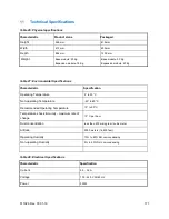
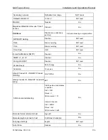
Page 171: ...Characteristic Specification Operating Temperature 5 to 35 C Non operating Temperature 40 to 60 C Recommended Operating Temperature 10 to 30 C Temperature shock immunity maximum rate of change 10 C p...

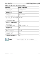
Page 172: ...e Over voltage category OVC OVCII Mains supply tolerance or absolute mains supply values 10 6 Tested for IT power systems No IT testing phase phase voltage V N A Class of equipment Class I Considered...

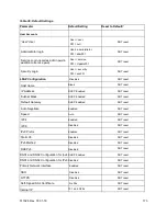
Page 173: ...P Address DHCP Enabled NOT reset Subnet Mask DHCP Enabled NOT reset Default Gateway DHCP Enabled NOT reset Auto Negotiate Enabled NOT reset Speed Auto NOT reset IPV4 Enabled NOT reset IPV6 Disabled NO...

Page 174: ...T reset Time Zone GMT NOT reset E mail Notifications SMTP Disabled Yes SNMP v1 v2 v3 Disabled Yes Encryption KMIP Disabled NOT reset Screen Saver Default image Yes Activation 10 minutes Yes Library Pr...

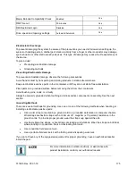
Page 175: ...e before removing them from their containers Avoid touching pins leads or circuitry Always be properly grounded when touching a static sensitive component or assembly See the next section Grounding Me...

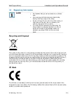
Page 176: ...roduct must not be disposed of with your other household waste Instead it is your responsibility to dispose of your equipment by handling it over to a designated collection point for the recycling of...

Page 177: ...n Although the equipment has been tested and found to comply with the allowed RF emission limits as specified in the above cited Rules there is no guarantee that interference will not occur in a parti...

Reviews: