background image

LIMITED WARRANTY

Conditions and Products Covered:

Quadrax guarantees any part of the product or accessory manufac-

tured by Quadrax and found in the reasonable judgment of Quadrax 

to be defective in material and or workmanship.

For replacement parts, only standard ground freight services are 

covered. 

This warranty extends to the original retail purchaser only and is not 

transferable to any subsequent purchasers.

Conditions and Products Covered:

(From date of the original retail purchase):

Residential use:  1 year

Commercial or rental use: 90 days

Items and Conditions Not Covered:

This warranty does not cover the following:

Pick-up or delivery charges or in-home services fees.

Expedited freight fee services for replacement parts.

Any damage or deterioration of the unit, parts and or finish of these, 

due to normal use, wear and tear, or exposure to weather, to 

chemicals or corrosive products.

Any part or accessory which has been altered, modified, misused, 

neglected, accidentally damaged or not properly installed, main-

tained, stored or repaired not in accordance with the instructions in 

the owner’s manual.

Repair due to normal wear and any wear items such as shear bolts, 

skid shoes, scaper blade, bolts, springs etc.

Shear bolts are to be considered as a preventive measure not as an 

assured protection, any damages resulting from the lack of shear 

bolts breakage are not covered.

Owner’s Responsibilities:

This warranty extends only to equipment operated under normal 

conditions.  To validate a warranty claim, it is the user’s responsibil-

ity to maintain and service the unit as specified in the owner’s 

manual or to have the unit serviced at their dealer at their expense.

General Conditions:

The sole liability of Quadrax with respect to this warranty shall be 

strictly and exclusively the replacement of defective parts as 

mentioned herein.  

Quadrax shall not have any liability for any other costs, loss or 

damage, including but not limited to any incidental or consequential 

loss or damage.

In particular, without being limited, to Quadrax shall have no 

liability or responsibility for:

Travel time, overtime, after hour’s time or other extraordinary repair 

charges or relating to repairs and or replacements outside of 

normal business hours.

Rental or like or similar replacement equipment during the period of 

any, repair or replacement work.

Any communicating or travel charges

Loss or damage to person or property other than that covered by 

the terms of this warranty.

Any claims for loss revenue, lost profit or any similar costs as a 

result of damage or repair.

Legal fees.

Quadrax’s responsibility in respect to claims is limited to making the 

required replacement without charge, up to our maximum labor 

rates and pre-established time, and no claim of breach of warranty 

shall be cause for cancellation or rescission of the contract of sale 

of any product or accessory.

This warranty gives you specific legal rights and you may also have 

other rights which vary from province to province.

Note:  Quadrax reserves the right to change or improve the design of any part or accessory without assuming any obligation to modify any 

product previously manufactured.

Instructions for Obtaining Warranty Services:

Contact dealer where equipment was purchased or any other Service Dealer to arrange service at their dealership.  

Bring the product and your proof of purchase (sales receipt) to the Quadrax dealer.

10

Summary of Contents for Q-LOCK

Page 1: ...unting system OWNER S MANUAL ASSEMBLY INSTRUCTIONS Push tube with universal attachment and articulated arm ALL TERRAIN VEHICLES UTILITY VEHICLES CAUTION Please read all safety and operation instructio...

Page 2: ...Secure the plow blade assembly to the ATV p15 step 7 8 Installation of the chains stabilizer p16 step 9 10 Installing pulley p17 step 11 Installing pulley continued p18 step 11 OPERATION To turn the...

Page 3: ...up your snowbanks The frame is equipped with a shock absorbing device that minimizes the possibility of damages that might be caused to the ATV in the event of a collision between the plow and a xed...

Page 4: ...nd 2 You must ensure that once the coupling hook is mounted to the hook mount and the hitch ball mount that the bottom of the coupling hook is as close as possible to the ground without affecting the...

Page 5: ...lcat 1000 HO 13 00 120 00 Brute Force 650 4x4I 9 70 86 40 Ranger 800 crew 11 50 145 00 BENNCHE Brute Force 650 4x4 7 30 86 00 Ranger 6x6 7 20 120 00 Bighorn 500 9 60 117 40 KVF 360 9 80 81 30 Ranger 8...

Page 6: ...s and insist that they be followed by those who will use this attachment THIS SAFETY ALERT SYMBOL IDENTIFIES AN IMPORTANT SAFETY MESSAGE IN THIS MANUAL THAT HELPS YOU AND OTHERS AVOID PERSONAL INJURY...

Page 7: ...he parking brake turn off the ATV and engines and remove the keys Do not clear snow across the face of the slopes Exercise extreme caution when changing direction on slopes Do not attempt to clear ste...

Page 8: ...manual or to have the unit serviced at their dealer at their expense General Conditions The sole liability of Quadrax with respect to this warranty shall be strictly and exclusively the replacement of...

Page 9: ...d Before making the final assembly check condition of the parts and that the nuts and bolts are tight B C D A F E Hook mount hitch ball assembly 1 A Front mounting tube rotation plate assembly 1 B Pus...

Page 10: ...e hitch ball mount or the ATV UTV 2 receiver hitch Not included Step 2 Warning You must ensure that once the coupling hook F is mounted on the hook mount A you have enough clearance between the unders...

Page 11: ...mounting tube and rotation plate assembly A between the two posts B of the snow blade Align the holes in the rotation plate with the holes of the two posts of the snow blade then secure in place usin...

Page 12: ...r 10 x 110mm bolts D eight washers E and four nuts F then to the rear frame channel using eight 10 x 30mm bolts G sixteen washers E and height nuts F Tighten firmly Note You have multiple adjustment p...

Page 13: ...and lock into place with the hitch pin and clip E Step 8 Attach one end of the retaining chain assembly A to the two L brackets holes B using the quick connecting links Then wrap the other end into t...

Page 14: ...with nut L Note You must modify or remove the driveshaft guards on some ATV models to install the anchor straps G J H K L J Step 9 Attach the chains stabilizer A to the upper anchor plate holes C usin...

Page 15: ...or ATV UTV Slide the push tube under and at the center of the vehicle Attach the strap A to the tube of the front bumper in a loop around the pipe Pull out the winch cable Attach the hook B to the st...

Page 16: ...separately This optional accessory is for controlling the locking action of the T handle pin in order to A Pull out the winch cable Attach the hook B to the strap A Make a bend C with the cable above...

Page 17: ...he tube B Sit on the bike and from this position find visual cues to remind you of the position of the plow when it is raised to the maximum IMPORTANT Never exceed the maximum height Ignoring this war...

Page 18: ...s equipped with a shock absorption system that reduces the risk of damage that could be caused to the ATV UTV If you hit a foreign object or ice the safety bolt is designed to break upon absorbing imp...

Page 19: ...low support 165 1102 1 2 Spring 165 1105 2 3 Plow stopper 165 1104 2 4 Hex bolt M10x30 165 B8437 2 5 Shoulder bolt M10 165 B8414 2 6 Washer M12 165 B8413 2 7 Hex Bolt M8x30 165 B8430 4 8 Washer M8 x 3...

Page 20: ...1 4 T handle 165 1244 1 5 Washer M16 165 B8499 1 6 Rear tube 165 1202B 1 7 Pivot 165 1202A5 1 8 Cutter pin 4x28 165 B8474 1 9 Hitch pin clip 165 1213 1 10 Receiver pin 165 1214 1 1 11 Springs 165 210...

Page 21: ...bilizer anchorage bracket assembly 1 2 165 1237 Chains stabilizer assembly 2 2 165 1238 Chains 15 links 3 2 165 1239 A arm mounting strap 4 4 165 1241 Quick connecting link 5 2 165 1242 Turnbuckle 6 1...

Page 22: ...14 16 16 13 16 15 13 16 165 1201A 1 165 1201A Push chanel assembly 12 1 165 1201 Push chanel 13 8 165 B8437 Hex bolt M10x30 14 4 165 B8442 Hex bolt M10x115 15 12 165 B8456 Locknut M10 16 24 165 B8493...

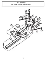
Page 23: ...PARTS BREAKDOWN IMPACT FRAME COUPLING HOOK AND MOUNT 25 17 19 20 25 25 22 20 25 21 24 16 7 8 3 9 10 4 23 2 18 1 12 11 12 15 13 14 6 5 12 11 12 Loctite...

Page 24: ...act absortion frame assembly 16 1 165 1340A mpact frame fr 17 1 165 1340B mpact frame rr 18 1 165 B8402 ALLEN bolt M10x25 19 1 165 B8436 Hex bolt M6x115 20 2 165 B8437 Hex bolt M10x30 21 1 165 B8451 L...

Page 25: ...ION PART NUMBER QTY I TEM Strap 165 35121 1 1 Pulley 165 35122 1 2 Spindle 165 35123 1 3 Shim 165 35124 2 4 Side plate 165 35125 2 5 Shackle 165 1233 1 6 Retaining ring 165 B8497 2 7 Side plate w bush...

Page 26: ...5 1002B ITEM QTY PART NUM DESCRIPTION 1 1 165 1001 Cable clamp retaining bracket 2 1 165 1002 Cable clamp assembly 1 165 1002A Clamping plate ext 1 165 1002B Clamping plate int 3 1 165 1003 Cable adju...

Page 27: ...ITCH AND HITCH BALL MOUNT 29 1 1 3 2 4 4 ately ITEM QTY PART NUM DESCRIPTION 1 1 2 receiver hitch 2 1 147 1228 Ball mount 3 4 rise 3 1 147 1107 Ball mount 2 drop 147 1109 Ball mount 3 1 4 drop 4 1 147...

Page 28: ...0260 15 1350 356 1187 TS Series ALL ALL 15 90100 RZR 900XP 2011 15 1351 Gator HPX 05 11 15 90150 SUZUKI KAWASAKI KingQuad 400FS 08 11 15 85180 15 1334 KSV650A Brute Force 4x4 07 10 15 85160 15 1345 35...

Page 29: ...3 4 Frame extension kit is sold separately This optional accessory allows you to extend the lengh of the plow frame for 114 to 144 ITEM QTY PART NUM DESCRIPTION 1 1 165 12021A Frame extension 2 8 165...

Page 30: ...x 1 25 225 169 333 242 377 284 M10 x 1 50 37 28 53 40 62 47 M12 x 1 75 65 49 93 69 108 81 M14 x 2 00 104 78 148 111 173 130 M16 x 2 00 161 121 230 172 269 202 M18 x 2 50 222 167 318 238 372 279 M20 x...

Reviews: