


Page 6
7001-142C
November 2, 2005
Santa Fe Pellet Stove
R
R
R
E. Inspect Appliance & Components and
Pre-Use Check List
Reciprocating Saw
Channel Locks
Hammer
Phillips Screwdriver
Tape Meausre
Plumb Line
Level
Framing Material
Hi-temp Caulking Material
Gloves
Safety Glasses
Framing Square
Electric Drill & Bits (1/4”)
1/4” Self-Tapping Screws
May also need:
Vent Support Straps
Venting Paint
Tools and building supplies normally required
for installation, unless installing into an existing
masonry fireplace:
C. Tools And Supplies Needed
Inspect appliance and components for
damage. Damaged parts may impair safe
operation.
WARNING
• Do NOT install damaged components.
• Do NOT install incomplete components.
• Do NOT install substitute components.
Report damaged parts to dealer.
• Installation and use of any damaged appliance.
• Modification of the appliance.
• Installation other than as instructed by Hearth & Home
Technologies.
• Installation and/or use of any component part not approved
by Hearth & Home Technologies.
• Operating appliance without fully assembling all
components.
• Operating appliance without legs attached (if supplied
with unit).
• Do NOT Overfire -
Or any such action that may cause a fire hazard.
WARNING
Hearth & Home Technologies disclaims any
responsibility for, and the warranty will be
voided by, the following actions:
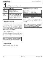
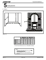
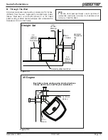
D. Measuring Standards
1. Pipe measurements are from center line to center line.
2. Vertial terminations are measured to top of pipe.
Figure 6.1
Measure horizontal
clearances from
this surface
Measure vertical
clearances from
this surface
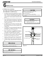
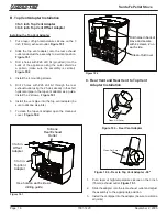
1.
Place the appliance in a location near the
final installation area and follow the proce-
dures below:
2.
Open the appliance and remove all the parts
and articles packed inside the Component
Pack. Inspect all the parts and glass for ship-
ping damage. Contact your dealer if any irregu-
larities are noticed.
3.
All safety warnings have been read and fol-
lowed.
4.
This Owner’s Manual has been read.
5.
Floor protection requirements have been met.
6.
Venting is properly installed.
7.
The proper clearances from the appliance and
chimney to combustible materials have been
met.
8.
The masonry chimney is inspected by a profes-
sional and is clean, or the factory built metal
chimney is installed according to the manufac-
turer’s instructions and clearances.
9.
The chimney meets the required minimum
height.
10.
All labels have been removed from the glass
door.
11.
Plated surfaces have been wiped clean, if
applicable.
12.
Thermostat or remote has been installed.
13.
A power outlet is available nearby.