


5
09/20
7058-804C
Recommended
Location
Marginal
Location
Location
Not
Recommended
Recommended
Location
Location NOT
Recommended
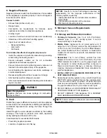
Multi-level Roofs
Windward
Leeward
Outside Air Kit Termination Cap
Figure 5.1
Install Guide
2
Getting Started
A. Design, Installation & Location Considerations
1. Appliance Location
Since pellet exhaust can contain ash, soot or sparks, you
must consider the location of:
• Windows
• Air Intakes
• Air Conditioner
•
Overhang, soffits, porch roofs, adjacent walls
• Landscaping, vegetation
• Horizontal or vertical vent termination
2. Floor Support
The supporting floor under the appliance must be able to
handle the weight of the appliance, fuel load and the weight
of the chimney.
Ensure that your floor will support these weights prior to
installation. Add sufficient additional support to meet this
weight requirement prior to installation. The weight of the
appliance is 240 lbs.
WARNING
Risk of Fire.
Damaged parts could impair safe operation. Do NOT
install damaged, incomplete or substitute components.
NOTICE:
Check building codes prior to installation.
• Installation MUST comply with local, regional, state and
national codes and regulations.
• Consult insurance carrier, local building inspector,
fire officials or authorities having jurisdiction over
restrictions, installation inspection and permits.
It is a good idea to plan your installation on paper, using
exact measurements for clearances and floor protection,
before actually beginning the installation. Location of the
appliance and chimney will affect performance.
Consideration must be given to:
•
Safety, convenience, traffic flow
• Placement of the chimney and chimney connector and
to minimize the use of chimney offsets.
• Place the appliance where there will be a clear
passage for a Listed chimney through the ceiling and
roof (vertical) or through exterior wall (horizontal).
• Installing the required outside air kit will affect the
location of the vent termination.
When locating vent and venting termination, the ideal
location is to vent above roof line when possible. This
minimizes the affects of wind loading.


