Quadra-Fire PS35-C Installation Manual Download Page 17

17

09/20

7058-804C

C. Negative Pressure

Negative pressure results from the imbalance of air available 

for the appliance to operate properly. It can be strongest in 

lower levels of the house.

Causes include:

•  Exhaust fans (kitchen, bath, etc.)
•  Range hoods
• Combustion air requirements for furnaces, water 

appliances and other combustion appliances

•  Clothes dryers
•  Location of return-air vents to furnace or air conditioning
•  Imbalances of the HVAC air handling system
•  Upper level air leaks such as: 

-  Recessed lighting

-  Attic hatch
-  Duct leaks

To minimize the effects of negative air pressure:

•  Install the outside air kit with the intake facing prevailing 

winds during the heating season

• Ensure adequate outdoor air for all combustion 

appliances and exhaust equipment

•  Ensure furnace and air conditioning return vents are not 

located in the immediate vicinity of the appliance

•  Avoid installing the appliance near doors, walkways or 

small isolated spaces

•  Recessed lighting should be a “sealed can” design
•  Attic hatches weather stripped or sealed
•  Attic mounted duct work and air handler joints and seams 

taped or sealed

NOTE:

 Follow venting manufacturers recommendations 

for sealing pipe joints.

D. Draft 

Draft is the pressure difference needed to vent an appliance 

successfully. When an appliance is drafting successfully, all 

combustion byproducts are exiting the home through the 

chimney.
Install through the warm airspace enclosed by the building 

envelope. This helps to produce more draft, especially 

during lighting and die-down of the fire.

Considerations for successful draft include:
•  Preventing negative pressure
•  Location of appliance and chimney

E. Minimum Vacuum Requirements

.065 inches W.C.

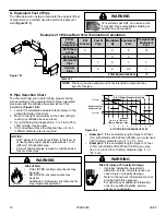
F. Chimney and Exhaust Connection 

1. 

Chimney & Connector

:  Use 3 or 4 inch (76-102mm)  

diameter type “L” or “PL” venting system. It can be 

vented vertically or horizontally.
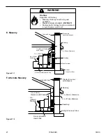
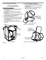
2. 

Mobile Home: 

Approved for all Listed pellet vent. If 

using the 3 inch (76mm) vertical Top Vent Adapter Kit 

or the 3 to 6 inch (76-152mm) Top Vent Offset Adapter, 

use  Listed  double  wall  flue  connector.  A  Quadra-Fire 

Outside Air Kit must be used with manufactured home 

installations.

3. 

Residential: 

The 3 inch (76mm) vertical Top Vent 

Adapter Kit and the 3 to 6 inch (76-152mm) Top Vent 

Offset Adapter  are  tested  to  use  24  gauge  single  wall 

flue  connector  or  Listed  double  wall  flue  connector  to 

Class A Listed metal chimneys, or masonry chimneys 

meeting International Residential Code standards for 

solid fuel appliances.

4. 

INSTALL VENT AT CLEARANCES SPECIFIED BY THE 

VENT MANUFACTURER.

5.  Seal exhaust venting system to the unit with High Temp 

500ºF RTV silicone sealant. Secure the venting system 

to the unit with at least (3) screws. All pellet vent pipe 

must be secured together either by means provided by 

the pipe manufacturer or by (3) screws at each joint.

6.  DO NOT INSTALL A FLUE DAMPER IN THE EXHAUST 

VENTING SYSTEM OF THIS Appliance.

7.  DO  NOT  CONNECT  THIS Appliance  TO A  CHIMNEY 

FLUE SERVING ANOTHER APPLIANCE.

NOTICE:

 Hearth & Home Technologies assumes no 

responsibility for the improper performance of the 

chimney system caused by:

•  Inadequate draft due to environmental conditions

•  Down drafts

•  Tight sealing construction of the structure

•  Mechanical exhausting devices

WARNING

Risk of Asphyxiation!

Negative pressure can cause spillage of combustion 

fumes and soot.

Summary of Contents for PS35-C

Page 1: ...esult causing property damage personal injury or death WARNING Do not store or use gasoline or other flammable vapors and liquids in the vicinity of this or any other appliance Do not over fire If app...

Page 2: ...Started A Design Installation Location Considerations 5 B Thermostat Wall Control Location 6 C Tools And Supplies Needed 6 D Inspect Appliance and Components 6 E Install Checklist 7 3 Dimensions and...

Page 3: ...ted Efficiency 68 8 EPA BTU Output 8 600 to 29 700 per hour BTU Input 12 600 to 41 900 per hour Vent Size 3 or 4 Type L or PL Hopper Capacity 45 lbs Fuel Premium Wood Pellets Weighted average LHV Low...

Page 4: ...composed of any combination of the following Steel Plaster Brick Iron Concrete Tile Glass Slate Materials reported as passing ASTM E 136 Standard Test Method for Behavior of Metals in a Vertical Tube...

Page 5: ...ir safe operation Do NOT install damaged incomplete or substitute components NOTICE Check building codes prior to installation Installation MUST comply with local regional state and national codes and...

Page 6: ...the installation to ensure maximum safety and benefit Follow pipe manufacturer instructions for installation and air clearance requirements Risk of Fire Damaged parts could impair safe operation Do N...

Page 7: ...ng this checklist for your file That this checklist remain visible at all times on the appliance until the installation is complete Electrical 120 VAC unswitched power provided to the appliance Check...

Page 8: ...ns Figure 8 3 Front View Figure 8 1 Top View Figure 8 2 Side View 2 1 4 in 59mm 2 1 4 in 59mm 8 7 8 in 224mm 8 7 8 in 224mm 9 1 2 in 243mm 12 1 2 in 318mm 20 1 4 in 514mm 31 3 4 in 806mm 22 1 4 in 565...

Page 9: ...o 4 inch Offset Adapter 811 0720 Figure 9 4 Side View w Top Vent Adapter TPVNT 5 3 to 4 inch Offset Adapter 811 0720 Figure 9 1 Top View w Top Vent Adapter TPVNT 5 3 in 77mm 5 in 128mm 11 1 8 in 284mm...

Page 10: ...2 Side View w Top Vent Adapter TPVNT 5 3 to 6 inch Offset Adapter 812 3570 Figure 10 4 Side View w Top Vent Adapter TPVNT 6 11 1 8 in 284mm 4 1 4 in 109mm 7 3 8 in 189mm 3 in 77mm 2 7 8 in 74mm 2 7 8...

Page 11: ...Vent Adapter TPVNT 6 3 to 4 inch Offset Adapter 811 0720 Figure 11 2 Side View w Top Vent Adapter TPVNT 6 3 to 4 inch Offset Adapter 811 0720 8 7 8 in 224mm 3 1 4 in 81mm 3 1 4 in 81mm 5 1 4 in 132mm...

Page 12: ...Back Wall to Adapter 1 25 E Side Wall to Appliance 14 356 F Back Wall to Appliance 6 1 4 159 Corner Installation Inches Millimeters G Walls to Appliance 2 51 Vertical Installation Inches Millimeters...

Page 13: ...r protection extending beneath the flue pipe is required with horizontal venting or under the Top Vent Adapter with vertical installation Figure 13 1 Figure 13 2 Figure 13 3 Figure 13 4 C Hearth Pad R...

Page 14: ...Depth n a n a 48 1219 D To Side Wall 14 356 n a n a All minimums listed are to a combustible surface A C B B D Table 14 1 Figure 14 2 Figure 14 1 NOTE Illustrations reflect typical installations and...

Page 15: ...parts of the structure P 12 in Clearance above roof line for vertical terminations All minimum clearances are listed with an Outside Air Kit OAK installed unless otherwise noted in table below 24 in A...

Page 16: ...d may consume the air needed for the appliance It may be necessary to add additional ventilation to the space in which the pellet appliance is located Consult with your local HVAC professional to dete...

Page 17: ...cessful draft include Preventing negative pressure Location of appliance and chimney E Minimum Vacuum Requirements 065 inches W C F Chimney and Exhaust Connection 1 Chimney Connector Use 3 or 4 inch 7...

Page 18: ...re 18 2 1 Locate the calculated equivalent feet of pipe on the vertical left side of the chart 2 Move to the right horizontally on the chart until you reach your altitude above sea level 3 If you fall...

Page 19: ...D VENT The following may occur The appliance will not vent properly Smoke spillage in the house Excessive sooting CAUTION Straight Out 45 Degree NOTICE Please note that while the minimum clearance for...

Page 20: ...tructions for all reduced air clearances installations B Vertical into Existing Class A Chimney Figure 20 3 Figure 20 2 D Through The Wall Vertical External C Vertical Interior Typical Installation PR...

Page 21: ...T WARNING Non combustible Hearth Pad Airtight Clean out Door Sheathing 2 in 51mm Minimum Flashing 1 in 25mm Clearance 1 in 25mm Clearance with Firestop 6 in 152mm Minimum Fireclay Flue Liner with Airs...

Page 22: ...re 22 2 1 Measure distance from floor to air vent opening in appliance and mark location on wall 2 Use a saw to cut opening in wall 2 inch kit Cut a 2 1 2 to 3 inch opening on inside wall and a 3 to 3...

Page 23: ...et using the 2 holes already in the short horizontal pipe in the top vent adapter as a guide Install the 2 screws Figure 23 1 6 Install the vent pipe into the top vent adapter 7 To clean the top vent...

Page 24: ...the thermostat from the mounting plate by gently pulling the two pieces apart c Slide thermostat wires through the back of the mounting plate Figure 24 3 d Connect your thermostat wire to the terminal...

Page 25: ...UTION THE STRUCTURAL INTEGRITY OF THE MOBILE HOME FLOOR WALL AND CEILING ROOF MUST BE MAINTAINED Do NOT cut through Floor joist wall studs or ceiling trusses Any supporting material that would affect...

Page 26: ...26 09 20 7058 804C A Service Maintenance Log 8 Reference Materials Date of Service Performed By Description of Service...

Page 27: ...27 09 20 7058 804C Date of Service Performed By Description of Service...

Page 28: ...28 09 20 7058 804C Date of Service Performed By Description of Service...

Page 29: ...29 09 20 7058 804C Date of Service Performed By Description of Service...

Page 30: ...Vertical Runs Only PEL DAMP3 Y Damper 4 PEL DAMP4 Outside Air Kit 3 OAK 3 Outside Air Kit 2 811 0872 Hose Alum Flex 2 Inch X 3 Ft 3 Ft SRV200 0860 Outside Air Cap Assembly 7001 044 Outside Air Collar...

Page 31: ...it 1 4 20 3 8 16 Rivnut Tools RIVNUT REPAIR Y Bolt Hex Head Pkg of 10 25221A 10 Y Guide Pin Sleeve Pkg of 25 31120 25 Y Hurricane Screw Pkg of 40 SRV2005 861 40 Nut SER FL SMALL 1 4 20 Pkg of 24 226 0...

Page 32: ...maintenance instructions included Read understand and follow these instructions for safe installation and operation Leave this manual with party responsible for use and operation of this appliance We...

Reviews: