


16
09/20
7058-804C
B. Avoiding Smoke and Odors
Negative Pressure, Shut-Down and Electrical
Power Failure
To reduce the probability of back-drafting or burn-back
in the pellet appliance during power failure or shut down
conditions, it must be able to draft naturally without exhaust
blower operation.
Negative pressure in the house will resist this natural draft if
not accounted for in the pellet appliance installation.
Heat rises in the house and leaks out at upper levels. This
air must be replaced with cold air from outdoors which
flows into lower levels of the house.
Vents and chimneys into basements and lower levels of the
house can become the conduit for air supply and reverse
under these conditions.
Outside Air
An outside air kit is recommended in all installations. The
Outside Air Kit must be ordered separately.
Per national building codes, consideration must be given
to combustion air supply to all combustion appliances.
Failure to supply adequate combustion air for all appliance
demands may lead to back-drafting of those and
other appliances.
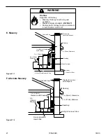
When the appliance is roof vented (strongly recommended):
The air intake is best located on the exterior wall
oriented towards the prevailing wind direction during
the heating season.
When the appliance is side-wall vented:
The air intake is best located on the same exterior wall
as the exhaust vent outlet and located lower on the wall
than the exhaust vent outlet.
The outside air supply kit can supply most of the demands
of the pellet appliance, but consideration must be given to
the total house demand.
House demand may consume the air needed for the
appliance. It may be necessary to add additional ventilation
to the space in which the pellet appliance is located.
Consult with your local HVAC professional to determine the
ventilation demands for your house.
CAUTION
•
DO NOT CONNECT THIS Appliance TO A CHIMNEY
FLUE SERVICING ANOTHER APPLIANCE.
•
DO NOT CONNECT TO ANY AIR DISTRIBUTION
DUCT OR SYSTEM.
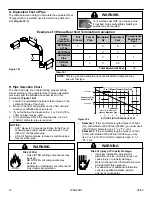
Vent Configurations
When installing a pellet appliance with a horizontal vent
configuration the frequency of power outages should
be considered:
• Power outages during operation will cause the
appliance to immediately turn off and may create
conditions where smoke will back draft into the house.
In order to reduce the likelihood of smoke back drafting
into the house during a power outage, Hearth and
Home Technologies strongly suggests:
- Installing the pellet venting with a minimum vertical
run of 5 feet (1.52m).
- Installing the outside air kit at least 4 feet (1.22m)
below the vent termination.
To prevent soot damage to exterior walls of the house and
to prevent re-entry of soot or ash into the house:
•
Maintain specified clearances to windows, doors and
air inlets, including air conditioners.
•
Vents should not be placed below ventilated soffits.
Run the vent above the roof.
• Avoid venting into alcove locations.
• Vents should not terminate under overhangs, decks or
onto covered porches.
• Maintain minimum clearance of 12 inches (305mm)
from the vent termination to the exterior wall. If
you see deposits developing on the wall, you may
need to extend this distance to accommodate your
installation conditions.
Hearth & Home Technologies assumes no responsibility
for, not does the warranty extend to, smoke damage
caused by reverse drafting of pellet appliances under
shut down or power failure conditions.


