Page 17
March 2000
GB 40 I - FIREPLACE INSERT
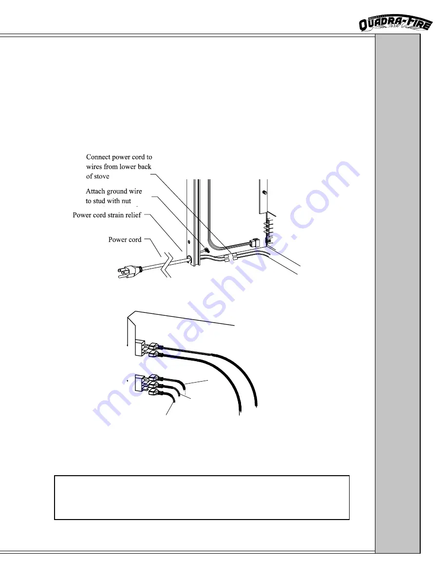
Tan Thermo Wires
White
Black
Red
INST
ALLA
TION:
BLOWER
BLOWER POWER CORD
The blower cord can be routed from either side of the panel set to a three prong grounded outlet. To
attach the power cord to the insert, locate the black and white wires at the rear of the insert. Attach
them to the black and white wires on the power cord (black to black, white to white). The green wire on
the power cord should be attached to the weld stud with nut (see diagram) on the panel as a ground. Be
sure that the appliance is electrically grounded in accordance with local codes, with a current version of
CSA C22 (in Canada), or in the absence of local codes, with the National Electric Code ANSI/NFPA 70-
1987.
SPEED CONTROL/ROCKER SWITCH CONNECTION
The speed control wires are located at the right rear of the appliance. Attach the two tan
thermo wires to the rocker switch; attach the white, black and red wires to thethree prong
blower switch as shown.
WARNING
Do not cut the grounding terminal off under any circumstances.
Do not route the power cord under the body of the appliance due to high temperatures.


