background image

Руководство пользователя 

5. BIOS parameter setting description 

123 


www.qtech.ru 

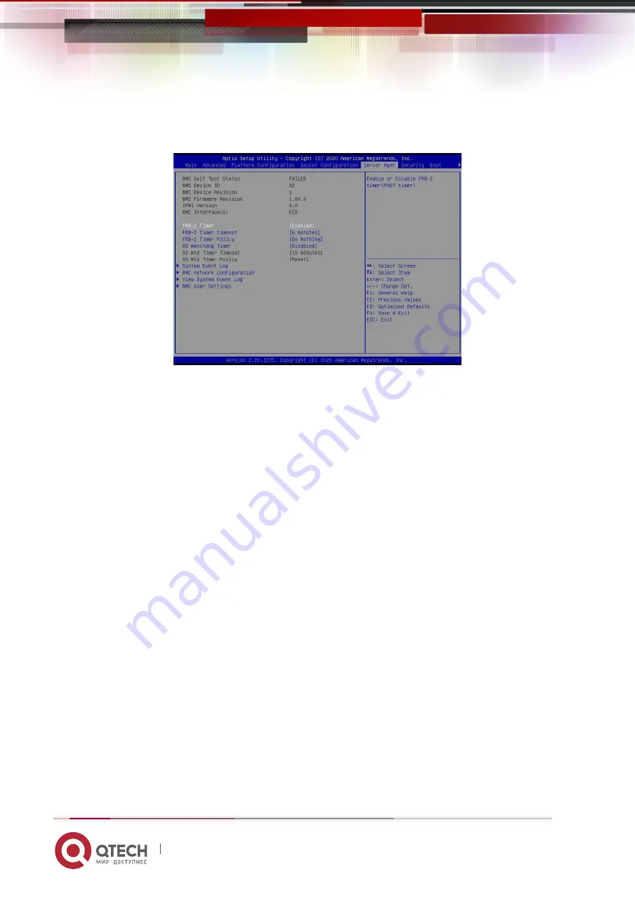
5.2.38 Server Mgmt menu 


Figure 5-39


Display  BMC self-check status, device ID,  device  version, BMC software version,  and 
support IPMI specification version. 


FRB-2 Timer 

FRB-2 clock switch settings, the menu options are: 

  Enabled : 

turn on


  Disabled : 

Off 


Default value: Enabled 


FRB-2 Timer timeout 

FRB-2 clock timeout setting, the menu options are: 

  3 minutes 

  4 minutes 

  5 minutes 

  6 minutes 

Default value: 6 minutes 


FRB-2 Timer Policy 

The policy setting after FRB-2 clock timeout, the menu options are: 

  Do Nothing 

  Reset 

Summary of Contents for QSRV-26 Series

Page 1: ...www qtech ru QTECH QSRV 26xxxx platform 2U manual server barebones...

Page 2: ...using this product Chapter 2 Product Introduction This chapter provides the specifications of the main components of the system and describes the main features of each model of the Purley 2U dual cab...

Page 3: ...mation obtained through this user manual Due to product version upgrades or other reasons the contents of this user manual will be updated from time to time Unless otherwise agreed this user manual is...

Page 4: ...tion 8038 fan Fan with size 80x80x38mm LGA3647 The full name Land Grid Array grid array package LGA3647 represents 3647 Contacts CR2032 It is a 3V CR2032 lithium manganese battery shaped like a button...

Page 5: ...ogy Attachment Serial ATA interface specification SAS Serial Attached SCSI Serial SCSI sSATA secondary SATA Expansion SATA interface LAN Local Area Network local area network VGA Video Graphics Array...

Page 6: ...mory module LRDIMM Load Reduced DIMM Low load DIMM AEP Apache Pass Intel Optane DDR4 memory code name MEZZ CONN Mezzanine Connector Mezzanine buckle card KVM Keyboard Video Mouse Can access and contro...

Page 7: ...pointing to a certain position Blue arrow represents the action of pulling out or inserting downward or tilting Hollow arrow represents the next action or result Dark blue rotating arrow 1 represents...

Page 8: ...2 2 2 System structure 19 2 3 System model specification introduction 21 2 4 System component introduction 25 2 4 1 Front panel components 25 2 4 2 Rear panel components 29 2 4 3 Motherboard componen...

Page 9: ...avigation key description 71 5 2 2 Main menu description 72 5 2 3 Advanced menu description 74 5 2 4 Trusted Computing 76 5 2 5 Serial Port Console Redirection 77 5 2 6 Console Redirection Settings 78...

Page 10: ...System Event Log menu 125 5 2 40 BMC network configuration menu 127 5 2 41 View System Event Log menu 130 5 2 42 BMC User Setting 131 5 2 43 Add User 132 5 2 44 Delete User 133 5 2 45 Change User Set...

Page 11: ...I function 216 7 1 3 IPMI interface configuration Static mode 219 7 1 4 IPMI configuration Java SOL 219 7 2 IPMI function quick start instructions 220 7 2 1 Enter the operation interface 220 7 2 2 Def...

Page 12: ...n for confirmation If you need twisting table cable wiring please contact QTECH to provide suggestions Please use a three core power cord and socket with grounding protection Improper grounding may ca...

Page 13: ...time QTECH is not responsible for data loss caused by any circumstances The optical drive used in this product is a Class 1 laser device Figure 6 1 1 2 Product name and content identification table o...

Page 14: ...1 Security Statement 14 www qtech ru motors etc Printed Circuit Components PCA X O O O O O Cable wire con nector X O O O O O Hard disk drive X O O O O O Table 1 1...

Page 15: ...ance in all homogeneous materials of this part is below the limit requirement stipulated in GB T26572 2011 Limit Requirements for Restricted Substances in Electronic and Electrical Products X Indicate...

Page 16: ...figurations have been tested for performance at 45 C temperature and 90 29 C maximum dew point humidity Temperature Operating temperature 10 C to 35 C 50 F to 95 F the maximum temperature gradient is...

Page 17: ...are not sure of the cause of the failure please contact the technical support department of QTECH for help Choosing a suitable environment for the computer is helpful for the stable operation of the c...

Page 18: ...lity high reliability easy management and easy deployment 2 2 System Configuration Nebulas 2 Purley 2U dual channel L shaped server products include 2U8 3 5 hard disk disk bays 2U12 3 5 hard disk The...

Page 19: ...fan N 1 hot swappable redundant fans The internet 2 Gigabit 10 Gigabit RJ45 network ports safety Support TPM module Chassis opening intrusion detection managem ent The onboard iBMC management module...

Page 20: ...herboard using 88E1512 chip from PCH Southbridge PCH uses INTEL LEWISBURG C621 C622 series chipset PCH leads to 14 SATA Ports the highest rate 6Gb s compatible with SATA 1 5Gb s 3 0Gb s SATA Controlle...

Page 21: ...n Scalable series processors Maximum support 205W Motherboar d model G3DCL B G3DCL TB chipset Intel C621 C622 series server dedicated chipset RAM system Support DDR4 LRDIMM RDIMM NV DIMM ECC memory Me...

Page 22: ...AS SATA HDD SSD Onboard 3 8643 interface 2 SATA DOM Optical drive Support 1 optical drive M 2 SSD 2 M 2 PCIE X2 2280 LAN Onboard 2 Gigabit RJ45 data network ports optional 2 Gigabit RJ45 data Network...

Page 23: ...sk processor Support 1 or 2 Intel Xeon Scalable series processors maximum support 205W Motherboar d model G3DCL B G3DCL TB chipset Intel C621 C622 series server dedicated chipset RAM system Support DD...

Page 24: ...ptical drive Support 1 optical drive M 2 SSD 2 M 2 PCIE X2 2280 LAN Onboard 2 Gigabit RJ45 data network ports optional 2 Gigabit RJ45 data network ports External port Front port VGA 2 USB3 0 Rear VGA...

Page 25: ...nel components Figure 2 4 2U8 disk bay 3 5 inch disk model Serial number name Serial number name 1 Built in DVD drive 3 USB3 0 interface 2 VGA interface 4 3 5 inch hard drive Table 1 7 2U12 disk bay 3...

Page 26: ...a display terminal such as a monitor or KVM USB interface USB 3 0 Provide an outgoing USB interface through which USB devices can be connected note When using an external USB device please make sure t...

Page 27: ...10 LED status description Logo Indicator light button State description Power indicator description Green steady light indicates that the device has been powered on normally Green flashing indicates t...

Page 28: ...is button to Turn on off the positioning light Reset button Press to restart the server Hard Disk Indicator Green light flashes the hard disk is operating normally System alarm indicator System alarm...

Page 29: ...network port is not in use or is faulty Note Corresponding to two 1GE network ports on the motherboard Table 1 11 2 4 2 Rear panel components Figure 2 7 Serial number name Serial number name 1 Rise mo...

Page 30: ...1000Mbit s Ethernet port The server can be managed through this interface USB interface USB 3 0 2 Provide an outgoing USB interface through which USB devices can be connected note When using an exter...

Page 31: ...Description of indicators and buttons on the rear panel Figure 2 8 Serial number name Serial number name 1 Connection status indicator 4 Data transmission status indicator 2 Data transmission status i...

Page 32: ...the input is normal and the power supply has turned off the output due to power on or in position input overvoltage or undervoltage Green 4Hz flashing indicates that the firmware is being upgraded on...

Page 33: ...2 Product Introduction 33 www qtech ru Figure 2 9...

Page 34: ...t 12G b SAS hard disk Maximum support 6G b SATA hard disk Supports hot swap of SAS SATA hard disks Table 1 16 Bottom surface Figure 2 11 Serial number description Features 1 2 3 4 Temperature control...

Page 35: ...nagement bus is used to connect and communicate between the backplane and the motherboard Table 1 17 2U8 expansion backplane as shown TOP noodles Figure 2 12 Serial number description Features SAS0 7...

Page 36: ...mission 3 4 SFF 8643 12Gb SAS interface Backplane bay signal interface 5 6 7 8 Temperature control fan socket For 4pin fan interface Table 1 19 SAS SATA backplane as shown TOP noodles Figure 2 14 Seri...

Page 37: ...Temperature sensor chip 2 5 7PIN SATA interface SATA disk signal line interface 3 I2C interface For I2C signal interface 4 SGPIO lighting signal Used for hard disk LED positioning and fault LED indic...

Page 38: ...38 www qtech ru TOP noodles Figure 2 16 Serial number description Features 1 SFF 8639 connector Support PCIe 4 U 2 interface used to connect NVME SSD Table 1 22 Bottom surface Figure 2 17 Serial numb...

Page 39: ...BMC I2C signal 2 CPLD chip For data logic processing 3 JATG debug interface JTAG debugging interface used to edit CPLD Process and version upgrade 4 Power outlet 4 Pin power socket used to dock PSU or...

Page 40: ...ion connector for 12V power supply Transmission 4 PCIE X16 specification gold finger For QTECH G3DCL motherboard PCIe X16 X8 interface 5 PCIE X8 specification gold hand Means For QTECH G3DCL motherboa...

Page 41: ...face 3 PCIE X8 gold finger For QTECH G3DCL motherboard PCIe X16 X8 interface Table 1 25 Figure 2 20 Serial number description Features 1 PCIE X16 Slot Used for PCIe 3 0 X16 devices 2 PCIE X8 Slot Used...

Page 42: ...4 5 Slimline interface For Slimline cable interface Table 1 27 2 4 5 DIMM slot location The motherboard uses the Intel Purley platform with Intel Xeon SkyLake CPU supports 12 DDR4 Channels 24 DDR4 slo...

Page 43: ...t Introduction 43 www qtech ru Figure 2 22 2 4 6 Hard disk label 2U8 disk bay 3 5 inch disk model Figure 2 23 2U12 disk bay 3 5 inch disk model Figure 2 24 2 4 7 Hard Disk Indicator Fault LED StatusLE...

Page 44: ...c OFF OFF Hard disk positioning Chang Liang Flashing 4Hz sec OFF Hard disk error Chang Liang OFF Chang Liang RAID reconstruct ion Chang Liang OFF Flashing 1Hz sec Table 1 28 2 4 8 System fan The serve...

Page 45: ...one end of the clamping piece 2 Direction press the other end of the clamp to fix the CPU to the clamp Figure 3 1 Figure 3 2 Step 2 Install the CPU on the radiator to ensure that the surfaces of the C...

Page 46: ...eat sink with the heat sink fixing studs on the CPU base and tighten the fixing screws of the heat sink in sequence according to the instructions As shown below Note The pins on the motherboard are ex...

Page 47: ...MMB1 B2 DIMM C1 C2 and DIMM D1 D2 The 8 memory slots controlled by CPU 2 are DIMME1 E2 DIMMF1 F2 DIMMG1 G2 and DIMMH1 H2 Note that the notch of the memory is consistent with the notch of the DIMM slot...

Page 48: ...ountersunk screws on the left and right sides to lock the hard drive the screw heads must not protrude from the surface of the slide rails on both sides of the tray Figure 3 8 Figure 3 9 Install 2 5 i...

Page 49: ...tall the hard drive tray assembly into the chassis 1 With the hard drive wrench open push it into the chassis 2 When the hard disk golden finger touches the backplane device turn the wrench in the dir...

Page 50: ...right sides of the hard disk backplane with the hanging nails of the hard disk frame and push in the direction of the arrow 2 After the hard disk backplane is pushed into place press the backplane do...

Page 51: ...3 Installing System Components 51 www qtech ru Figure 3 14 Figure 3 15...

Page 52: ...the positioning studs according to the length of the M 2 card to be installed Figure 3 16 Step 2 install M 2 card 1 Insert the M 2 card connector end into the motherboard connector as shown in the fig...

Page 53: ...p 3 Install the fixing screws of the M 2 card Figure 3 18 3 7 PCI E module installation Riser1 3 module installation steps the rear window PCIE components vertically downward align the PCIE slot align...

Page 54: ...3 8 Rear hard disk module backplane installation Step 1 Install the rear hard disk module backplane 1 Pull the back plate limiting shrapnel outward with your hand and hold the shrapnel with your hand...

Page 55: ...as shown in the figure the fixing parts can be placed flat Figure 3 21 Figure 3 22 3 9 Rear hard disk module installation Rear 3 5 inch HDD tray installation Step 1 Place the HDD tray vertically down...

Page 56: ...qtech ru Figure 3 23 Figure 3 24 Rear 2 5 inch HDD tray installation 1 Place vertically downward aiming at the guide pin at the lower end 2 After placing it flat push it to the end in the direction o...

Page 57: ...3 Installing System Components 57 www qtech ru Figure 3 25 Figure 3 26...

Page 58: ...qtech ru 3 10 Power supply module installation Step Push the power supply in the direction of the arrow to the end and the shrapnel wrench on the right makes a clicking sound indicating that it is ins...

Page 59: ...www qtech ru 3 11 PCI E expansion card installation Steps install PCIE card 1 Install the PCIE card in the direction indicated in the figure 2 Rotate the PCIE card lock 3 Follow the arrow scheme to l...

Page 60: ...3 Installing System Components 60 www qtech ru Figure 3 30 Figure 3 31...

Page 61: ...ling System Components 61 www qtech ru 3 12 Fan module installation Steps The fan module is placed vertically downward in the direction of the arrow note the direction of the fan module Figure 3 32 Fi...

Page 62: ...s 62 www qtech ru 3 13 Installation of air duct Steps align the air baffle module with the hanging points on the left and right sides and place it vertically downward the height is lower than the heig...

Page 63: ...ation Step install the optical drive 1 The optical drive is as shown in Figure 3 34 Figure 3 35 2 Align the opening of the optical drive on the chassis and push the optical drive in the direction of t...

Page 64: ...3 Installing System Components 64 www qtech ru Figure 3 37...

Page 65: ...on of the upper cover of the chassis Step 1 Install the back cover of the chassis 1 Align the top cover with the opening position of the box and place it down 2 Rotate the upper cover lock in the dire...

Page 66: ...t Installation 66 www qtech ru 4 SYSTEM CABINET INSTALLATION 4 1 Rail installation Step 1 Prepare two sliding rail frames and draw out the inner rail Figure 4 1 Step 2 Fix the inner rails on both side...

Page 67: ...4 System cabinet Installation 67 www qtech ru Figure 4 2...

Page 68: ...all the outer rail to cabinet Step 3 Install the outer rail on the cabinet bracket and tighten the screws Note When installing the guide rail you need to align the U mark and install it in place with...

Page 69: ...hear a pop If you can t push it you need to pull the inner rail buckle down to continue pushing the chassis gently Figure 4 4 Step 5 When the chassis is pushed forward and cannot slide the screws are...

Page 70: ...4 System cabinet Installation 70 www qtech ru Figure 4 5...

Page 71: ...BIOS Setup interface at the bottom left of the Logo screen Press DEL or ESC to enter setup F7 to enter Boot Menu 3 Press the keyboard DEL or ESC key to prepare to enter the BIOS Setup interface 5 2 S...

Page 72: ...BIOS version information of the board 5 2 2 2 Build Date and Time Display the compilation date and time of the board BIOS 5 2 2 3 BMC Firmware Revision Display the BMC version information of the board...

Page 73: ...stem Language Select the current system language 5 2 2 16 System Date Display and set the current system date The format of the system date is week month day year Press Enter to switch between month d...

Page 74: ...5 BIOS parameter setting description 74 www qtech ru 5 2 3 Advanced menu description The Advanced interface contains advanced configuration items of the BIOS system Figure 5 2...

Page 75: ...tion SIO configuration Option ROM Dispatch Policy Option ROM call policy PCI Subsystem Settings PCI Subsystem Settings CSM Configuration CSM configuration NVMe Configuration NVMe configuration Network...

Page 76: ...ting description 76 www qtech ru 5 2 4 Trusted Computing Figure 5 3 Display and set the TCM TPM module information Different module options have different settings The user can set according to the Se...

Page 77: ...ion Figure 5 4 Console Redirection The console redirection function switch redirects the information output from the console such as a graphics card to the display to the serial port Disabled Turn off...

Page 78: ...through this option and the BIOS emulation type must match the mode selected in the terminal program The menu options are VT100 VT100 VT UTF8 ANSI Default value VT100 Bits per second Serial port redir...

Page 79: ...efault value 1 Flow Control Serial port redirection control flow selection switch the menu options are None Close the serial port redirection control flow Hardware RTS CTS Request to send Clear to sen...

Page 80: ...5 BIOS parameter setting description 80 www qtech ru Enabled open Disabled Closed Default value Disabled 5 2 7 SIO Configuration Figure 5 6...

Page 81: ...Disabled Closed Default value Enabled Possible Choose the optimal settings for the serial port according to your needs the menu options are Use Automatic Settings IO 3F8h IRQ 4 DMA IO 3F8h IRQ 3 4 5 7...

Page 82: ...ault value Disabled Primary Video Ignore Ignore the basic graphics card the menu options are Enabled open Disabled Closed Default value Enabled On Board Mass Storage Controller Onboard or external dev...

Page 83: ...the menu options are Enabled open Disabled Closed Default value Enabled Slot 1 Empty Onboard or external device controller the menu options are Enabled open Disabled Closed Default value Enabled Slot...

Page 84: ...ings Figure 5 9 Above 4G Decoding Memory space resource decoding control switch above 4G the menu options are Enabled open Disabled Closed Default value Enabled SR IOV Support SR IOV supports switch s...

Page 85: ...e menu options are Disabled shut down Enabled Open Default value Enabled GateA20 Active A20 address line control mode setting the menu options are Upon Request If needed Always always Default value Up...

Page 86: ...witch the menu options are UEFI and Legacy UEFI and Legacy startup items UEFI only UEFI boot item Legacy only Legacy boot item Default value UEFI and Legacy Option ROM Policy Select Option ROM executi...

Page 87: ...5 BIOS parameter setting description 87 www qtech ru Figure 5 11 Display the detailed information of the NVMe hard disk...

Page 88: ...5 BIOS parameter setting description 88 www qtech ru 5 2 13 Network Stack Configuration Figure 5 13...

Page 89: ...v4 HTTP function control switch the menu options are Enabled open Disabled Closed Default value Disabled Ipv6 PXE Support Ipv6 UEFI PXE function control switch the menu options are Enabled open Disabl...

Page 90: ...iption 90 www qtech ru Media detect count The number of device detection times the user can enter the number of device network card device detection times the default is 1 5 2 14 iSCSI Configuration F...

Page 91: ...igure 5 15 PCH SATA Configuration PCH SATA related configuration PCH sSATA Configuration PCH sSATA related configuration USB Configuration USB related configuration Miscellaneous Configuration other r...

Page 92: ...controller the menu options are Disabled Turn off the SATA controller Enabled Turn on the SATA controller Default value Enabled Configure SATA as SATA mode selection the menu options are AHCI Select...

Page 93: ...d Port X Control the opening and closing of SATA Port X the menu options are Disabled Close SATA Port X Enabled Enable SATA Port X Default value Enabled Hot Plug Control the hot plug function of SATA...

Page 94: ...Enabled Turn on the sSATA controller Default value Enabled Configure sSATA as sSATA mode selection the menu options are AHCI Select sSATA mode as AHCI mode RAID Select sSATA mode as RAID mode Default...

Page 95: ...sSATA Port X Enabled Enable sSATA Port X Default value Enabled 5 2 18 USB Configuration Figure 5 18 USB Per Connector Disable Each USB connector switch the menu options are Enable open Disable Turn o...

Page 96: ...o press the Power button to power on leave power state unchanged leave power state unchanged Default value S0 Max Page Table Size Select Select the maximum page table size setting the menu options are...

Page 97: ...ch ru 5 2 20 Server ME Configuration Figure 5 20 Display Server ME version features status and other information 5 2 21 Runtime Error Logging Figure 5 21 System Errors Turn on or off the system error...

Page 98: ...Figure 5 22 Processor Configuration processor related configuration Common RefCode Configuration Common RefCode configuration UPI Configuration UPI configuration Memory Configuration memory configura...

Page 99: ...5 23 Figure 5 24 Display CPU Type ID Speed Cache and other information configure CPU related functions Pre Socket Configuration each slot configuration Hyper Threading Hyper threading control switch...

Page 100: ...the menu options are Enable open Disable Turn off Default value Disable VMX CPU virtualization technology switch enable this option then the virtualization layer or operating system that supports this...

Page 101: ...When the application scenario is to access memory sequentially enabling this feature will improve performance When the application scenario is random access to memory it is recommended to disable thi...

Page 102: ...2KB 8Way Without ECC Extended APIC Enable disable extended APIC support the menu options are Enable open Disable Turn off Default value Disable AES NI Turn AES Advanced Encryption Standard on and off...

Page 103: ...High Base Select MMIO high base address the menu options are 56T 40T 24T 16T 4T 1T Default value 56T MMIO High Granularity Size Select MMIO high interval size the menu options are 1G 4G 16G 64G 256G...

Page 104: ...can reduce the feature by setting Topology Precedence or you can reduce the Topology by setting Feature Precedence the menu options are Topology Precedence Topology first Feature Precedence Feature p...

Page 105: ...cluster settings the menu options are Disable shut down Enable Open open Auto Automatic Default value Disable XPT Prefectch XPT prefetch settings the menu options are Disable shut down Enable Open ope...

Page 106: ...R settings the menu options are Auto Automatic POR Perform POR Disable Off Default value Auto Memory Frequency Memory frequency setting the menu options are Auto Automatic 800 1000 1066 1200 1333 1400...

Page 107: ...able switch setting the menu options are Disable shut down Enable Open the default value Enable Legacy ADR Mode Traditional ADR mode switch settings the menu options are Disable shut down Enable Open...

Page 108: ...nterleaved NVDIMMs switch settings the menu options are Disable shut down Enable Open the default value Disable 2x Refresh Enable 2x refresh switch settings the menu options are Disable shut down Enab...

Page 109: ...5 BIOS parameter setting description 109 www qtech ru 5 2 27 Memory Topology Figure 5 28 Display the detailed information of the current memory...

Page 110: ...ions are 1LM 2LM Auto Default value Auto 1LM Memory Interleave Granularity 1LM Memory Interleave Granularity setting the menu options are Auto 256B Target 256B Channel 64B Target 64B Channel Default V...

Page 111: ...erleavel Default Value Auto Rank Interleaving Rank cross setting the menu options are Auto 1 way Interleavel 2 way Interleavel 4 way Interleavel 8 way Interleavel Default Value Auto Socket Interleave...

Page 112: ...are Enable turn on Disable Default value Disable Mirror Mode Mirror mode setting the menu options are Disable shut down Enable Mirror Mode 1LM Default value Disable UEFI ARM Mirror UEFI ARM mirroring...

Page 113: ...ch setting the menu options are Enable turn on Disable Default value Disable Set NGN Die Sparing Set NGN Die hot backup switch settings the menu options are Enable turn on Disable Off Default value En...

Page 114: ...rent link rate etc Intel R VT for Directed I O VT d Intel VT d technology related settings sub menu Intel VT d technology switch settings Intel R VMD Technology Intel VMD technology related settings s...

Page 115: ...SPM Support Global PCIE ASPM master switch setting the menu options are Disable shut down Per Port each port L1 Only L1 only Default value Per Port PCI E Max Read Request Size PCIE maximum read reques...

Page 116: ...control setting submenu Hardware PM State Control hardware power management state control submenu CPU C State Control CPU C status control setting submenu Package C State Control Package C state contr...

Page 117: ...sion setting the menu options are Enable turn on Disable Off Default value Enable Config TDP TDP level setting the menu options are Normal Normal Level 1 Level 1 Level 2 Level 2 Default value Normal T...

Page 118: ...ermined according to the actual test The options are Disable Hardware selection P States based on traditional OS request Native Mode Hardware selection P State is based on traditional OS boot Out of B...

Page 119: ...tings the menu options are Enable turn on Disable Default value Disable CPU C6 report Report the C6 status switch settings to the OS the menu options are Disable shut down Enable turn on Auto Automati...

Page 120: ...etting description 120 www qtech ru 5 2 35 Package C State Control Package C State Package C status setting the menu options are C0 C1 state C2 state C6 non Retention state C6 Retention state No Limit...

Page 121: ...5 BIOS parameter setting description 121 www qtech ru 5 2 36 CPU Advanced PM Tuning Figure 5 37 Energy Perf BIAS CPU power saving performance related option settings...

Page 122: ...djustment default value OS Controls EPB ENERGY_PERF_BIAS_CFG Mode Energy saving performance management settings This item can be set when Power Performance Tuning is set to BIOS Control EPB The menu o...

Page 123: ...rt IPMI specification version FRB 2 Timer FRB 2 clock switch settings the menu options are Enabled turn on Disabled Off Default value Enabled FRB 2 Timer timeout FRB 2 clock timeout setting the menu o...

Page 124: ...tting the menu options are 5 minutes 10 minutes 15 minutes 20 minutes Default value 10 minutes OS Wtd Timer Policy The policy setting after the OS watchdog clock timeout the menu options are Do Nothin...

Page 125: ...bled Closed Default value Enabled Erase SEL Clear system event record control switch menu options No do not clear Yes On next reset reset next time Yes On every reset Clear every restart Default value...

Page 126: ...ww qtech ru Log EFI Status Codes Configuration record EFI Status Codes menu options Disabled do not record Both Record Error code Progress code Error code Only record Error code Progress code Only rec...

Page 127: ...5 BIOS parameter setting description 127 www qtech ru 5 2 40 BMC network configuration menu Figure 5 41 Figure 5 42...

Page 128: ...n the option will restore the Unspecified value There is no need to configure the BMC IP every time you start the process When the Configuration Address source option is Unspecified the network parame...

Page 129: ...ue Enabeld Modify from Unspecified to other parameters save and restart after execution the option will restore the Unspecified value There is no need to configure the BMC IP every time you start the...

Page 130: ...ameter setting description 130 www qtech ru 5 2 41 View System Event Log menu Figure 5 44 View system event log information Note that when entering this menu BIOS needs to read the SEL data and it tak...

Page 131: ...5 BIOS parameter setting description 131 www qtech ru 5 2 42 BMC User Setting Figure 5 45 Add User Add user submenu Delete User delete user submenu Change User Setting submenu...

Page 132: ...lude uppercase and lowercase letters special characters and numbers with a minimum of 8 characters and a maximum of 20 characters Channal No BMC channel setting enter 1 or 8 User Privilege Limit User...

Page 133: ...r the name of the user to be deleted User Password Enter the password of the user to be deleted After entering the correct password a prompt User Delete will pop up The successfully deleted user will...

Page 134: ...can be modified User User permission switch settings the menu options are Enabled turn on Disabled Default value Disabled Change User Password To modify the user password the input password character...

Page 135: ...5 BIOS parameter setting description 135 www qtech ru User Operator Administrator...

Page 136: ...displays Installed there is no administrator Password display Not Installed User Password Display the user password status the system has a user password and it displays Installed If there is no user...

Page 137: ...process the menu options are On turn on OFF Off Default value On Quiet Boot Turn on and off the Quiet Boot function the menu options are Disabled Turn off Quiet Boot the POST message will be displaye...

Page 138: ...Boot Option Priorities Startup option list This list is displayed dynamically and is determined by the number of startup options in the system When there is no startup item it is not displayed XXXX D...

Page 139: ...t the BIOS setup menu Discard Changes and Exit Give up saving the settings and exit the BIOS setup menu Save Changes and Reset save the settings and restart the system Discard Changes and Reset give u...

Page 140: ...ription 140 www qtech ru Load BIOS factory settings Save as user Defaults save as user default settings Restore user Defaults reload user default configuration Boot Override Startup options list you c...

Page 141: ...eminder 1 With the option of you need to understand the operating specifications in detail when you need to operate 2 When operating options please understand the meaning of the options in conjunction...

Page 142: ...ress Delete Esc as prompted to enter the BIOS Setup interface 2 Move to the PlatForm page PCH Configuration PCH Sata Configuration Configure SATA as Configure SATA to RAID mode as shown in Figure 6 1...

Page 143: ...STe SATA Controller press enter to enter the configuration RAID as shown in Figure 6 3 Figure 6 3 Intel RSTe SATA Controller Figure 6 3 Create RAID 1 Select Create RAID Volume and press enter Figure 6...

Page 144: ...You can select the level of group raid as shown in Figure 6 6 Figure 6 6 Select the level of group RAID Figure 6 6 4 Select Disks Press the space bar to select the disks that need to participate in t...

Page 145: ...he Select Disks column press Enter Select the disk X means that the disk has been selected Strip Size Stripe size the size of striped data blocks written on each disk Capacity The capacity of the logi...

Page 146: ...hown in Figure 6 9 select Mark as Spare and press Enter Figure 6 9 Hot spare disk configuration interface Figure 6 9 3 Enter the interface shown in Figure 6 10 select Yes and press Enter to complete t...

Page 147: ...ace 2 As shown in Figure 6 11 select the RAID to be deleted in the RAID Volumes directory and press Enter Figure 6 11 Select the RAID to be deleted Figure 6 11 3 Enter the RAID information interface s...

Page 148: ...6 RAID Setting Instructions 148 www qtech ru Figure 6 12...

Page 149: ...Te onboard software RAID has two controllers SATA and sSATA which manage the disks connected to the two interfaces of the RAID card The SATA controller supports up to 8 disks and the sSATA controller...

Page 150: ...ter Configuration Utility will appear twice during the BIOS startup process corresponding to sSATA and SATA controllers in turn Please configure RAID according to the configuration Select the controll...

Page 151: ...e RAID Volume Delete RAID volume 3 Reset Disks to Non RAID Clear the RAID configuration information of the disk 4 Mark Disks as Spare Configure hot spare disks 5 Exit Exit Located at the bottom of the...

Page 152: ...er Description Name The name of the RAID RAID Level RAID level The RAID level determines the performance fault tolerance and capacity of the logical disk Disks Select the member disks that make up the...

Page 153: ...ct Mark Disks as Spare on the RSTe configuration interface and press Enter Figure 6 20 RSTe configuration interface Figure 6 20 3 Enter the interface shown in Figure 6 21 select the disk to be configu...

Page 154: ...s 154 www qtech ru Figure 6 21 4 In the RSTe configuration interface you can see the hot spare disk information as shown in Figure 6 22 Figure 6 22 View hot spare disk information on the RSTe configur...

Page 155: ...in Figure 6 23 select Delete RAID Volume on the RSTe configuration interface and press Enter Figure 6 23 RSTe configuration interface Figure 6 23 3 Enter the interface shown in Figure 6 24 select the...

Page 156: ...sks are displayed on the interface refer to Table 1 31 for related instructions Figure 6 25 RAID card configuration interface as shown in Figure 6 25 Figure 6 25 Table 1 31 Parameter description Optio...

Page 157: ...26 Common task switching disk mode The RAID card supports switching between the following three disk modes 1 Unconfigured Good indicates that the physical disk is normal and can be used to configure...

Page 158: ...Drive Management management interface Figure 6 27 3 Enter the interface shown in Figure 6 28 select Operation press Enter and then select Make Unconfigured Bad in the pop up dialog box and press Ente...

Page 159: ...ure 6 30 to complete the operation of switching the disk mode Figure 6 30 Finish switching disk mode Figure 6 30 6 2 2 Create RAID 1 As shown in Figure 6 31 select Configuration Management on the RAID...

Page 160: ...er the interface shown in Figure 6 32 select Create Virtual Drive and press Enter Figure 6 32 Select Create Virtual Drive Figure 6 32 3 Enter the interface shown in Figure 6 33 select Select RAID Leve...

Page 161: ...s Enter Unconfigured Capacity indicates that the capacity comes from the remaining capacity of the disk that has been configured with RAID Free Capacity means that the capacity comes from an empty dis...

Page 162: ...Enabled means selected then select Apply Changes and press Enter If the status of the disk is JBOD or Unconfigured Bad it cannot be selected Figure 6 36 7 Enter the interface shown in Figure 6 37 mak...

Page 163: ...the size of the striped data block written on each disk Read Policy The read cache strategy is divided into Read Ahead open read cache and No Read Ahead close read cache Save Write Policy Write cachi...

Page 164: ...as the name of the RAID Compared with No Read Ahead Write Through and Direct Read Ahead Write Back and Cached have improved performance but data consistency cannot be guaranteed If the super capacitor...

Page 165: ...igure 6 39 Complete RAID configuration Figure 6 39 10 As shown in Figure 6 40 select Virtual Drive Management on the RAID card configuration interface and press Enter Figure 6 40 RAID card configurati...

Page 166: ...ure 6 41 12 Enter the interface shown in Figure 6 42 select View Associated Drives and press Enter to view the detailed information of the RAID including RAID name level and disk information etc Figur...

Page 167: ...k is larger than the capacity of a single member disk of the RAID to contribute to the RAID Only the disk whose configuration mode is Unconfigured Good is supported as a hot spare disk Configure globa...

Page 168: ...er the interface shown in Figure 6 45 select Operation press Enter then select Assign Dedicated Hot Spare Drive and press Enter Figure 6 45 Operation interface Figure 6 45 4 Enter the interface shown...

Page 169: ...own in Figure 6 47 select Confirm to enable it select Yes and press Enter Figure 6 47 Confirm configuration Figure 6 47 6 Enter the interface shown in Figure 6 48 to complete the configuration of the...

Page 170: ...6 49 select Virtual Drive Management on the RAID card configuration interface and press Enter Figure 6 49 RAID card configuration interface Figure 6 44 2 Enter the interface shown in Figure 6 50 sele...

Page 171: ...ace shown in Figure 6 51 select Operation press Enter and then select Delete Virtual Drive in the pop up dialog box and press Enter Figure 6 51Operation operation interface Figure 6 51 4 Enter the int...

Page 172: ...5 Enter the interface shown in Figure 6 53 select Confirm to enable it select Yes and press Enter Figure 6 53 Confirm deletion Figure 6 53 6 Enter the interface shown in Figure 6 54 to complete the RA...

Page 173: ...hysical disk 1 1 As shown in Figure 6 55 select Drive Management on the RAID card configuration interface and press Enter Figure 6 55 Select Drive Management Figure 6 55 1 2 Enter the interface of Fig...

Page 174: ...nter the interface of Figure 6 57 select Operation press Enter and then select Start Locate in the pop up dialog box and press Enter Figure 6 57 Operation interface Figure 6 57 1 4 Enter the interface...

Page 175: ...ation of locating the physical disk position Figure 6 59 Finish positioning the physical disk location Figure 6 59 2 Locate all disks in the logical disk 2 1 As shown in Figure 6 60 select Virtual Dri...

Page 176: ...6 61 select the logical disk to be located and press Enter Figure 6 61 Select the logical disk to be located Figure 6 61 2 3 Enter the interface of Figure 6 62 select Operation press Enter and then s...

Page 177: ...er the interface of Figure 6 63 select Go and press Enter Figure 6 63 Select Go Figure 6 63 2 5 Enter the interface of Figure 6 64 to complete the operation of locating all disk positions in the logic...

Page 178: ...is used to initialize the internal data space of the logical disk so that it can be recognized and used by the operating system 1 As shown in Figure 6 65 select Virtual Drive Management on the RAID ca...

Page 179: ...6 66 3 Enter the interface shown in Figure 6 67 select Operation press Enter and then select Fast Slow Initialization in the pop up dialog and press Enter Figure 6 67 Operation interface Figure 6 67 T...

Page 180: ...ure 6 68 Select Go Figure 6 68 5 Enter the interface shown in Figure 6 69 select Confirm to enable it select Yes and press Enter Figure 6 69 Confirm initialization Figure 6 69 6 Enter the interface sh...

Page 181: ...shown in Figure 6 71 select Drive Management on the RAID card configuration interface and press Enter Figure 6 71 RAID card configuration interface Figure 6 71 2 Enter the interface shown in Figure 6...

Page 182: ...interface of Figure 6 73 select Operation press Enter and then select Initialize Drive in the pop up dialog box and press Enter Figure 6 73 Operation management interface Figure 6 73 4 Enter the inte...

Page 183: ...nterface shown in Figure 6 75 select Confirm to enable it select Yes and press Enter Figure 6 75 Confirm initialization Figure 6 75 6 Enter the interface of Figure 6 76 to complete the initialization...

Page 184: ...6 RAID Setting Instructions 184 www qtech ru Figure 6 76...

Page 185: ...e 6 77 select Drive Management on the RAID card configuration interface and press Enter Figure 6 77 RAID card configuration interface Figure 6 77 1 2 Enter the interface shown in Figure 6 78 select th...

Page 186: ...nter the interface shown in Figure 6 80 press Enter and then select the erase mode in the pop up dialog box It is recommended to use the default mode Simple Figure 6 80 Erase Mode interface Figure 6 8...

Page 187: ...erface shown in Figure 6 82 select Confirm to enable it select Yes and press Enter Figure 6 82 Confirm erasure Figure 6 82 1 7 Enter the interface shown in Figure 6 83 to complete the operation of era...

Page 188: ...ata 2 Erase logical disk data 2 1 As shown in Figure 6 84 select Virtual Drive Management on the RAID card configuration interface and press Enter Figure 6 84 RAID card configuration interface Figure...

Page 189: ...ss Enter and then select Virtual Drive Erase in the pop up dialog box and press Enter Figure 6 86 Operation interface Figure 6 86 3 Enter the interface shown in Figure 6 87 press Enter and then select...

Page 190: ...ru Figure 6 87 4 Enter the interface shown in Figure 6 88 select Go and press Enter Figure 6 88 Select Go Figure 6 88 5 Enter the interface shown in Figure 6 89 select Confirm to enable it select Yes...

Page 191: ...0 Completed erasing logical disk data Figure 6 90 6 2 6 Migrate RAID level This function is used to modify the RAID level to meet the configuration requirements without affecting the current data inte...

Page 192: ...t the logical disk to be rebuilt and press Enter Figure 6 92 Virtual Drive Management management interface Figure 6 92 3 Enter the interface shown in Figure 6 93 select Operation press Enter and then...

Page 193: ...u Figure 6 93 4 Enter the interface shown in Figure 6 94 select Go and press Enter Figure 6 94 Select Go Figure 6 94 5 Enter the interface shown in Figure 6 95 set the RAID level select Add Drives and...

Page 194: ...ce shown in Figure 6 96 select the disk to be added make it Enabled select Apply Changes and press Enter Figure 6 96 Add Drives interface Figure 6 96 7 Enter the interface shown in Figure 6 97 select...

Page 195: ...ch ru Figure 6 97 8 Enter the interface shown in Figure 6 98 select Start Operation and press Enter Figure 6 98 Start Operation interface Figure 6 98 9 Enter the interface shown in Figure 6 99 select...

Page 196: ...6 RAID Setting Instructions 196 www qtech ru Figure 6 99 10 Enter the interface shown in Figure 6 100 to view the current migration progress Figure 6 100 RAID information interface Figure 6 100...

Page 197: ...r disks whose mode is Unconfigured Bad 1 Switch the disk mode Unconfigured Bad to Unconfigured Good 2 As shown in Figure 6 101 select Configuration Management on the RAID card configuration interface...

Page 198: ...igure 6 103 Select Clear Foreign Configuration Figure 6 48 5 Enter the interface shown in Figure 6 104 select Confirm to enable it select Yes and press Enter Figure 6 104 Confirm clear Figure 6 49 6 E...

Page 199: ...6 RAID Setting Instructions 199 www qtech ru Figure 6 105...

Page 200: ...rl R Figure 6 106 Press Ctrl R as prompted during BIOS startup Figure 6 106 2 Enter the interface shown in Figure 6 107 Please refer to the key operation tips at the lower border of the interface to n...

Page 201: ...e Virtual Drive Figure 6 51 4 Enter the interface shown in Figure 6 109 set the RAID level and press Enter Figure 6 109 Set RAID level Figure 6 52 5 Enter the interface shown in Figure 6 110 select th...

Page 202: ...own in Figure 6 111 set the Size and Name accordingly then select Advanced and press Enter Figure 6 111 Set RAID name and capacity Figure 6 54 7 Enter the interface shown in Figure 6 112 set the relev...

Page 203: ...OK and press Enter to complete the RAID configuration operation Figure 6 113 Confirm creation Figure 6 56 9 Select the RAID to be viewed and press Enter to view the detailed information of the RAID in...

Page 204: ...6 RAID Setting Instructions 204 www qtech ru Figure 6 57...

Page 205: ...y of a single member disk of the RAID to contribute to the RAID Only the disk whose configuration mode is Unconfigured Good is supported as a hot spare disk 1 Configure global hot spare disk 1 1 As sh...

Page 206: ...206 www qtech ru Figure 6 59 1 3 Return to the interface shown in Figure 6 117 select the hot spare disk to view the related information of the global hot spare disk Figure 6 117 View global hot spare...

Page 207: ...cal disk to be deleted on the VD Mgmt interface and press F2 Figure 6 118 Select the logical disk to be deleted Figure 6 118 2 Enter the interface shown in Figure 6 119 select Delete VD and press Ente...

Page 208: ...6 RAID Setting Instructions 208 www qtech ru Figure 6 120...

Page 209: ...e disk A single physical disk or all member disks included in a logical disk can be located 1 As shown in Figure 6 121 select the disk to be located on the PD Mgmt interface and press F2 Figure 6 121...

Page 210: ...nitialize the internal data space of the disk so that it can be recognized and used by the operating system 1 As shown in Figure 6 123 select the disk to be initialized on the VD Mgmt interface and pr...

Page 211: ...the remaining space is initialized in the background FGI Full Groud Initialization full disk initialization initialize all the space of the RAID and write data after the initialization is completed 3...

Page 212: ...ect the physical disk to be erased on the PD Mgmt interface and press F2 Figure 6 126 Select the physical disk to be erased Figure 6 67 1 2 Enter the interface shown in Figure 6 127 select the erasing...

Page 213: ...f physical disk data 2 Erase logical disk data 2 1 As shown in Figure 6 129 select the logical disk to be erased on the VD Mgmt interface and press F2 Figure 6 129 Select the logical disk to be erased...

Page 214: ...ng Instructions 214 www qtech ru Figure 6 71 2 3 Enter the interface shown in Figure 6 131 select Yes and press Enter to complete the operation of erasing logical disk data Figure 6 131 Confirm erasur...

Page 215: ...de is Unconfigured Bad 1 Switch the disk mode Unconfigured Bad to Unconfigured Good 2 As shown in Figure 6 132 in the Foreign View interface select the RAID card press F2 select Foreign Config Clear a...

Page 216: ...choose to share the network port as shown in Figure 7 2 Figure 7 2 Main board dedicated network port 7 1 2 Enter BIOS to set IPMI function Restart your system and press ESC or DEL to enter the motherb...

Page 217: ...nfiguration option interface On this page you can see two configurable network ports one is Dedicated dedicated network port and the other is Sharelink shared network port Take the shared network port...

Page 218: ...four network modes that can be configured on this interface namely Unspecified Static DynamicBMCDHCP DynamicBMCNonDHCP Static is the static mode you can manually set the IP address and DHCP is the dyn...

Page 219: ...nagement 4 The IPMI port has the function of obtaining an IP address through DHCP 5 IPMI supports two protocols TCP IP v4 and TCP IP v6 Configure the IP address and subnet mask according to your actua...

Page 220: ...costs a lot of computer resources We recommend that the client configure more than 8G of memory when using KVM 7 2 1 Enter the operation interface Take the Google Chrome browser as an example Enter th...

Page 221: ...Factory default password admin When you log in with this user name you will have full administrator rights It is recommended that you change your password after logging in 7 2 3 IPMI management syste...

Page 222: ...s 2 sensor This page displays the status of all sensors When there is a sensor alarm the sensor will be displayed in the key sensor column When the alarm is released the sensor will be automatically r...

Page 223: ...r indicator light control 10 Mirror redirection On this page you can get the latest image file on the remote storage device 11 maintain You can perform basic maintenance operations on the server such...

Page 224: ...KVM Java SOL Remote Control menu Figure 7 11 Start KVM 7 2 5 KVM page introduction As shown in Figure 7 12 it is the KVM interface after starting KVM Figure 7 12 KVM interface As shown in Figure 7 13...

Page 225: ...7 IPMI Rapid Deployment 225 www qtech ru Figure 7 13 KVM interface composition...

Page 226: ...rating system the host display unlocks the server turns on and off Table 1 28 7 2 7 Introduction to SOL Click Activate Java SOL on the page shown in Figure 7 14 to open the interface shown in Figure 3...

Page 227: ...igure 7 15 SOL operation interface Note The SOL interface operation function has only tested the BIOS screen synchronization and other interfaces have not been tested This time is an operation demonst...

Page 228: ...ackage and you can also use the Open IPMI driver in the system AST2500 supports the Open IPMI driver of the Linux kernel Use the following command to load the IPMI driver modprobe ipmi_devintf modprob...

Page 229: ...DR4 ECC RDIMM LRDIMM server memory memory frequency support 1866 2133 2400 2666MHz Support 12 DDR4 Channel each Channel supports 2 DIMMs a total of 24 DDR4 slots supports Intel Optane 2933MHz memory I...

Page 230: ...is opening intrusion detection Lock the upper cover of the chassis The onboard iBMC management module supports management features such as IPMI SOL KVM Over IP and virtual media management Microsoft W...

Reviews: