10W HF Linear PA kit assembly
1.00
13
3.6 Wind and install transformer T202
T202 is wound on a BN61-2402 binocular core. It has a primary consisting of 3 bifilar turns, and a
secondary of a single 5-turn winding. First use a drill bit twisted by hand, to gently remove any
rough edges to the holes, that could cut into the wire.
Whilst the electrical definition of “primary” and “secondary” has swapped relative to T201 in the
previous section, the physical construction of the T202 transformer is very similar to T201. The
only difference is that the single-wire winding is 5 turns this time. Therefore, simply repeat the
procedure for winding the coil in the previous section, using 5 turns for the single-wire winding.
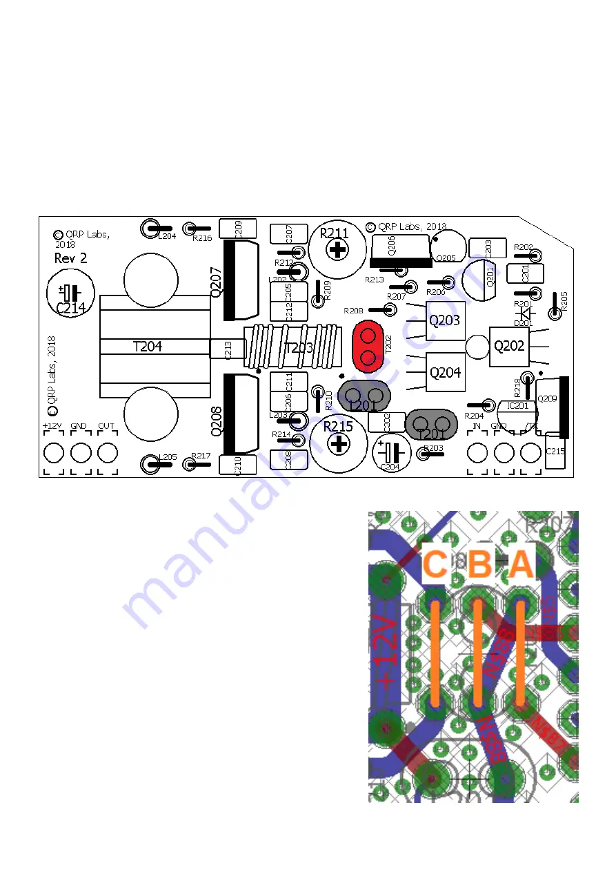
Similar to the previous section, let us identify the bifilar
windings as A and B, and the single-wire winding as C.
Again, untwist the bifilar winding ends and identify the
pairs of wires with the DC continuity test. Be sure to keep
the C winding (single-
wire) separate and don’t confuse it
with the other two windings.
Installation on the PCB in the T202 position is very similar
to T201, but rotated through 90-degrees. Again, match the
shape of the binocular core to the drawing on the PCB
silkscreen.
Again, test the windings A, B and C for continuity of the
wire ends, through the right pairs of holes A, B and C,
BEFORE soldering. Only when you are sure that all 6
wires are in their correct holes, proceed with cutting them
to 2mm protrusion and soldering them. Again solder the
wires for 10 seconds or more until the enamel has burned
off and a good joint is made. With these thin wires the
burning method is quite easy.
Now undertake the usual continuity test.


