


Chapter 3 Robot Debugging and Components Maintenance
Document Version V1.1.0 (03-07-2022)
19
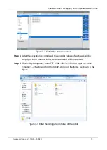
Step 2
Use scissors to cut off the cable ties at the rear end of the module.
Step 3
Disconnect the communication cable and power cable from the interface panel at
the rear end of the module. The cabling diagram of the module is shown in Figure 3-
8.
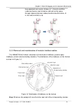
Figure 3-8 Module cabling diagram
For 48V power input of Axes J1~J3, connect the power cable
from the base power interface to the power input interface of the
module. The power output interfaces of Axes J1 and J2 are not
equipped with connectors, so pay attention to it during removal
and installation.
The Axis J6 module is a terminal module, and the power output
and signal output interfaces are not equipped with connectors,
so pay attention to it during removal and installation.
3.2.4 Removal and maintenance of ground wires
To ensure that the robot is internally well grounded, connect the axes J2 ~ J4 with ground
wires. If the modules of Axes J2 ~ J4 and other components are removed, the ground wires of
the corresponding axes need to be removed. The connection of ground wires of Axes J2 ~ J4
is shown in Figure 3-9.
Summary of Contents for MS6MT
Page 1: ......


