16
ENGLISH
Introduction
Rear Panel
2.2
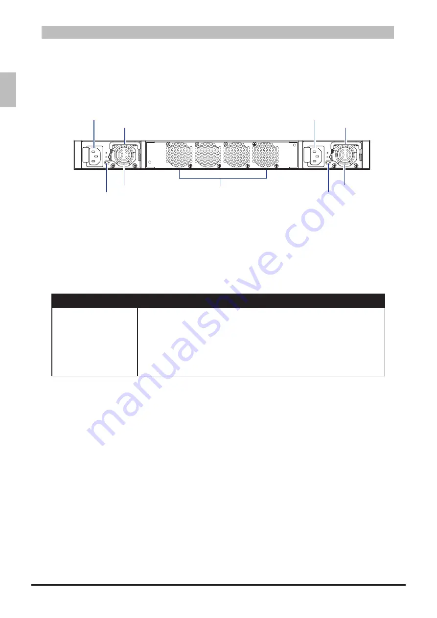
The following figure shows the rear panel of the switch.
Rear Panel View
Figure 2-6:
Fan Assembly
Handle
PSU2
PSU1
AC Power Connector
(with Plug Retainer)
Handle
AC Power Connector
(with Plug Retainer)
PSU2 LED
PSU1 LED
The switch has two Power Supply Units (PSU) and four fan modules. The fan modules can be built in
as back-to-front or front-to-back depending on customer requirements.
The AC power connector is a standard three-pronged connector. The switch automatically adjusts its
power setting to any supply voltage in the range from 100~240 VAC at 50~60 Hz.
When the PSU is connected to the power source, the PSU LED lights green.
Power Supply LEDs
Table 2-4:
LED
Description
Power Supply
Green
•
: Power connection works normally.
Yellow
•
: Possible issues:
- Fan Lock (15 sec)
- OTP: Over Temperature Process
- OCP: Over Current Process
- OVP: Over Voltage Process
- UVP: Under Voltage Process
Package Contents
2.3
The following items are included with a standard package. When you open the box, check if all items
are included and free of damage.
One LB9 Network Switch
•
Mounting kit: 2 mounting brackets and screws (already install on the switch)
•
Four rubber feet with adhesive backing
•
Console cable
•
Two AC power cords
•
Statement paper
•


