


User manual
• It is recommended not to use aluminum utensils for
cooking with osmotic water.
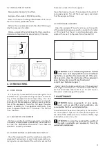
4. BASIC OPERATION
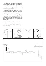
The mains water to be treated enters the equipment
through the sediment and carbon filter. In this stage of
filtration, suspended particles, chlorine, its derivatives
and other organic substances are retained.
The passage of water into the equipment is controlled
by means of an electric solenoid valve.
The water, after being treated in the filtration stage, is
pumped towards the reverse osmosis membrane. The
equipment incorporates a pump to increase the pres-
sure, since the pressure of the water on the membrane
makes the process of reverse osmosis possible.
The osmotic water comes out of the equipment throu-
gh the dispensing tap. Rejection water with excess salts
and other dissolved substances is directed into the dra-
in for disposal.
When you stop dispensing water through the tap, the
equipment stops its operation by means of a high pres-
sure switch.
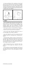
This equipment incorporates the turbine as a safety
device, which protects the pump from pressure drops,
stopping the equipment and preventing damage to the
pump.
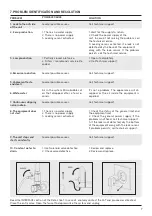
5. USER INTERFACE
ATTENTION: This equipment incorporates an elec-
tronic controller that will efficiently manage the
functionality and status indications in which it is loca-
ted, as well as the different security systems.
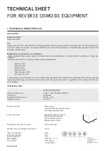
The technical data sheet of the equipment describes
the states in which the system can be found and the
information provided by it (pages 20-22 of this manual).
6. MAINTENANCE
In order to guarantee the quality of the water supplied
by your equipment, it must be kept regularly maintai-
ned.
Read the corresponding section of the Technical Ma-
nual to see the recommended maintenance frequency
(page 11 of this manual).
Summary of Contents for VYRTA direct flow
Page 1: ...1 USER MANUAL EQUIPMENT REVERSE OSMOSIS ...
Page 2: ......
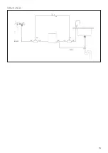
Page 13: ...13 IN FEED DRAIN 3 8 1 4 RO 3 8 1 4 1 4 1 4 1 4 Hydraulic scheme ...
Page 17: ...17 ...
Page 28: ...NOTES ...
Page 29: ...NOTES ...
Page 30: ...NOTES ...
Page 31: ...NOTES ...