background image

User Manual


PT-MA-HD42UHD 


5.3


EDID Setting 

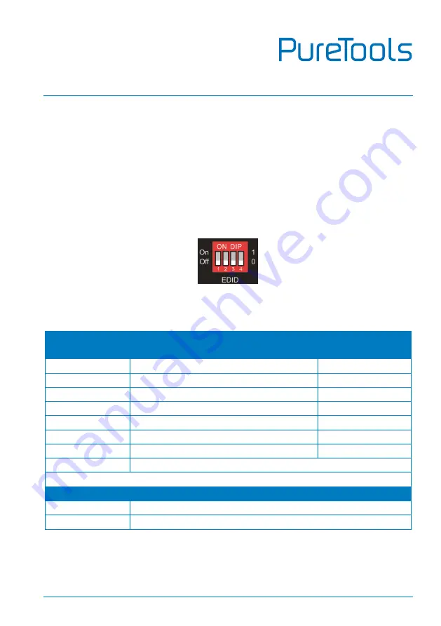
The Extended Display Identification Data (EDID) is used by the source device to match 
its video resolution with the connected display. The 4-pin DIP switch on the front 
panel can be used to set the EDID to a fixed value to ensure the compatibility in the 
video resolution. 

The switch represents “

0

” when in the lower (

OFF

) position, and it represents “

1

” 

while putting the switch in the upper (

ON

) position. 


Switch 1~3 are used for built-in EDID setting, and switch 4 is used for mode setting. 

The DIP switch status and its corresponding setting are shown as below chart. 

Switch 1~3 

Status 

Video Resolution 

Audio Format 

000 

Pass-through 

Pass-through 

001 

1920x1080@60Hz 8bit 

Stereo 

010 

3840x2160@30Hz 8bit 

Stereo 

011 

3840x2160@30Hz 8bit HDR 

Stereo 

100 

3840x2160@30Hz Deep Color HDR 

PCM 5.1 

101 

3840x2160@60Hz 8bit 

Stereo 

110 

3840x2160@60Hz Deep Color HDR 

PCM 5.1 

111 

User-defined EDID 


Switch 4 Status 

Mode 

Global Mode. 

Out B Private Mode. 


Summary of Contents for PT-MA-HD42UHD

Page 1: ...User Manual PT MA HD42UHD User Manual 4x2 HDMI 2 0 Presentation Switcher with Matrix Outputs Model PT MA HD42UHD Designed in Germany 2019 PureLink GmbH All rights reserved V1 0 ...

Page 2: ...opied or reproduced without the prior written consent FCC Statement This equipment generates uses and can radiate radio frequency energy and if not installed and used in accordance with the instructions may cause harmful interference to radio communications It has been tested and found to comply with the limits for a Class B digital device pursuant to part 15 of the FCC Rules These limits are desi...

Page 3: ... 1907 2006 EU und 2011 65 EU EMC LVD Electro Magnetic Compatibility Low Voltage Directive PureLink GmbH hereby declares that this product PureTools PT MA HD42UHD complies with Directives 2014 30 EU and 2014 35 EU The full text of the EU Declaration of Conformity is available at the following Internet address http www purelink de ce 4251364718353_CE pdf ...

Page 4: ...tall this product near water Do not put any heavy items on the extension cable in case of protrusion Do not remove the housing of the device as opening or removing the housing may expose you to dangerous voltage or other hazards Install the device in a place with sufficient ventilation to avoid damage caused by overheat Keep the module away from liquids Spillage into the housing may result in fire...

Page 5: ... 5 4 System Connection 6 5 Button Control 7 5 1 Manual Switching 7 5 2 Auto Switching 7 5 3 EDID Setting 8 6 IR Remote Control 10 7 Web Control 11 8 RS232 Control 13 8 1 RS232 Control Software 13 8 2 RS232 Communication Command 17 8 2 1 System Control Commands 18 8 3 Signal Switching Commands 20 8 4 EDID Setting Commands 21 8 5 Audio Setting Commands 21 9 Firmware Upgrade 22 ...

Page 6: ...ide range of control flexibility via Web RS232 IR and smart EDID management 1 1 Features 4x2 HDMI presentation switcher with matrix outputs HDMI 2 0b 4K 60Hz 4 4 4 8bit HDR 10 HDCP 2 2 4K to 1080p down scaling SPDIF and 3 5mm output for dual HDMI OUT audio extraction and dual HDMI OUT ARC RS232 IR and TCP IP control Smart EDID management 1 2 Package List 1x PT MA HD42UHD 1 x Power Adapter 12V DC 1...

Page 7: ...onnector 2 Type A Female HDMI Video output Video Resolution OUT A Up to 4K 60Hz 4 4 4 8bit HDR10 Dolby Vision supports color space 4 2 2 4 2 0 to 4 4 4 4K to 1080p down scaling OUT B Up to 4K 60Hz 4 4 4 8bit HDR Dolby Vision HDMI Output Cable 5 meters HDMI Version Up to 2 0 HDCP Version Up to 2 2 Digital SPDIF Audio Output Audio Output 1 Digital SPDIF audio Audio Output Connector 1 Toslink connect...

Page 8: ...vel or max level before clipping L R level deviation 0 05dB 1KHz sine at 0dBFS level or max level before clipping Output load capability 1Kohm and higher supports 10x paralleled 10Kohm loads Noise Level 80dB Control Part Control Port 1 EDID Switch 1 FW 1 RS232 1 IR IN 1 TCP IP Control Connector 1 4 pin DIP Switch 1 Micro USB 1 3 pin terminal block 1 3 5mm jack 1 RJ45 General Bandwidth 18Gbps Opera...

Page 9: ... indicate which source is selected Auto LED Illuminates green in auto switching mode Select Auto 3s Press the button repeatedly to cycle through the four video inputs Press and hold the button for 3 seconds to enter or exit auto switching mode Audio Out De embedded Two HDMI de embedded audio source LEDs one of which illuminates green to indicate output A or output B de embedded audio source is sel...

Page 10: ...udio Out Toslink connector and 3 5mm jack for audio output There are four audio can be selected output A de embedded audio output B de embedded audio output A ARC audio or output B ARC audio RS232 Connects to control device e g PC to control the switcher by sending RS232 commands IR EYE Connects to IR receiver to control the switcher by the IR remote TCP IP Connects to the control device e g PC to...

Page 11: ...n Scaler Audio Out 1 2 3 4 A B IR EYE OUT A AUTO 3 4 OUT B AUTO 3 4 1 2 1 2 AUDIO A B Game Console Game Console Blu ray Laptop 4K TV 4K TV 1080p TV Laptop Down scale ARC Soundbar Centre Control System Remote IR Receiver HDMI Audio RS232 IR TCP IP Outputs ARC Inputs DC 12V Tx Rx RS232 TCP IP Down Scaler Audio Out 1 2 3 4 A B IR EYE Amplifier Blu ray 4K TV 4K TV ARC ARC ARC ARC Soundbar HDMI ARC Aud...

Page 12: ...e for output B and then the Auto LED will turns green When in auto switching mode the switcher will switch according to the following rules The switcher will switch to the first available active input starting at input 1 to 4 New input The switcher will automatically select the new input once detecting a new input Reboot If power is restored to the switcher it will automatically reconnect the inpu...

Page 13: ...nts 1 while putting the switch in the upper ON position Switch 1 3 are used for built in EDID setting and switch 4 is used for mode setting The DIP switch status and its corresponding setting are shown as below chart Switch 1 3 Status Video Resolution Audio Format 000 Pass through Pass through 001 1920x1080 60Hz 8bit Stereo 010 3840x2160 30Hz 8bit Stereo 011 3840x2160 30Hz 8bit HDR Stereo 100 3840...

Page 14: ... of two outputs are same the input source device will not reread the EDID of display device to ensure non flash screen 2 When the specifications of output A and output B display devices are different set the EDID to Out B Private Mode and the Out A is in Pass through mode When switching the input source of output A to output B because the input source device will first learn the EDID from output B...

Page 15: ...nput source for OUT A AUTO Press the button to enable auto switching mode for OUT A 1 4 Press 1 4 button to select corresponding input source for OUT B AUTO Press the button to enable auto switching mode for OUT B De embedded Press A or B button to select output A or output B de embedded audio for audio output ARC Press A or B button to select output A or output B ARC audio for audio output ...

Page 16: ...ntrol The switcher can be controlled via TCP IP The default IP settings are IP Address 192 168 0 178 Subnet Mask 255 255 255 0 Type 192 168 0 178 in the internet browser it will enter the below log in webpage Username admin Password admin ...

Page 17: ...ol tab Matrix Switch Select Input 1 4 for output A or output B to build matrix switching Select AUTO to enable auto switching mode for output A or output B Audio Out Select output A de embedded audio output B de embedded audio output A ARC audio or output B ARC audio for Toslink and 3 5mm jack audio outputs ...

Page 18: ...ample Installation Please download the latest Software Version from the link below https docklight de download Docklight zip Then follow the installation wizard for installation on Windows 7 and 10 After the installation Docklight can be run for the first time and should look like the below screen shot Registration is not necessary unless you wish to save settings on exit so unless you wish to reg...

Page 19: ... up window can also be closed with Continue An empty project is enough to send and receive commands easily The default setting is always Start with a blank project blank script Click Continue to close this window Click OK to close this window ...

Page 20: ...ble click on COM1 in the corresponding setup window In the following window select the drop down menu labeled Send Receive on Comm Channel select the appropriate COM port and then click on OK at the bottom right corner All other settings can be left at default for most applications but refer to device RS232 settings to be sure Double click on COM1 to change to the right COM port ...

Page 21: ... clicking on Play 1 Then the keyboard function must be activated so that commands can be written in the communication window 2 Finally enter the command for example 50701 This is then confirmed by pressing Enter to send Any response from the connected device will appear in red 3 Select the right COM port ...

Page 22: ...ty bit none Note All commands needs to be ended with CR LF In the commands and are symbols for easy reading and do not need to be typed in actual operation Type the command carefully it is case sensitive Click Play to open the communication Enable the keyboard type in function Command sending area Monitoring area indicates if the command sent works 1 2 3 ...

Page 23: ...em reboot Reboot_True GetStatus Get device status SetIpAddr XXX XXX XXX XXX Set static IP address to XXX XXX XXX XXX IpAddr 192 168 0 178 GetIpAddr Get IP address IpAddr 192 168 0 178 SetRS232Baudrate PARAM Set the baud rate of switcher to PARAM PARAM 1 7 PARAM Baud Rate 1 115200 2 57600 3 38400 4 19200 5 9600 6 4800 6 2400 SetRS232Baudrate 5 RS232Baudrate 9600 GetRS233Baudrate Get the baud rate o...

Page 24: ...enabled and the switcher will automatically get IP again SetDhcp En Dhcp True GetDhcp Get DHCP status Dhcp True SetSubnetMask XXX XXX XXX XXX Set subnet mask to XXX XXX XXX XXX SubnetMask 255 255 255 0 GetSubnetMask Get subnet mask SubnetMask 255 255 255 0 SetGateWay XXX XXX XXX XXX Set gateway to XXX XXX XXX XXX GateWay 192 168 0 1 GetGateWay Get gateway GateWay 192 168 0 1 SetMacAddr XX XX XX XX...

Page 25: ...ode Dis Disable auto switching mode SetAutoSwitch B En AutoSwitch OutB True GetAutoSwitch Get the auto switching mode of output A and output B AutoSwitch OutA False AutoSwitch OutB True SetSignalDet PARAM Set the signal auto detection method to PARAM PARAM 5V TMDS The default detection method is 5V SetSignalDet 5V SignalDetMode 5V GetSignalDet Get the signal auto detection method SignalDetMode 5V ...

Page 26: ...scription Command Example and Feedback SetAudioSrc PARAM Set the audio source of analog audio and SPDIF audio PARAM 1 2 3 4 1 OUTA de embedded 2 OUTB de embedded 3 OUTA ARC 4 OUTB ARC SetAudioSrc 1 AudioSrc OutA De embedded SetSpdif PARAM Mute unmute the SPDIF audio output PARAM Mute UnMute SetSpdif Mute Spdif Mute SetIis PARAM Mute unmute the analog audio output 3 5mm jack PARAM Mute UnMute SetIi...

Page 27: ...ct a U disk named of BOOTDISK 3 Double click the U disk a file named of READY TXT would be showed 4 Directly copy the latest upgrade file bin to the BOOTDISK U disk 5 Reopen the U disk to check the filename READY TXT whether automatically becomes SUCCESS TXT if yes the firmware was updated successfully otherwise the firmware updating is fail the name of upgrade file bin should be confirm again and...

Page 28: ...ce Technical Support Phone 49 5971 800299 0 Fax 49 5971 800299 99 Technical Support Hours 8 30 AM to 5 00 PM Monday thru Thursday 8 30 AM to 4 00 PM Friday Write to PureLink GmbH Von Liebig Straße 10 D 48432 Rheine www purelink de info purelink de ...

Reviews: