background image


NAS System


16 

User Manual 


3.2.2  Installing 2

.5” Disk in a Disk Tray


a.


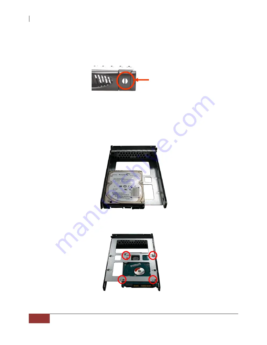
Make sure the lock indicator is in unlocked position. To pull out a disk tray, press 
the tray open button. 


b.


Pull out an empty disk tray. Pull the lever handle outwards to remove the carrier 
from the enclosure. 


c.


Place the 2.5” hard drive in the disk tray. 


d.


Install the mounting screws on the bottom part to secure the drive in the disk tray. 


e.


Slide the tray into a slot. 

f.


Close the lever handle until you hear the latch click into place.               

Tray Hole W 

Tray      

Open  
Button 

Summary of Contents for EN-1400A6B-CM

Page 1: ...NAS System User Manual Revision 1 0...

Page 2: ...ation 8 2 1 Unpacking the NAS System 8 2 2 Identifying Parts of the NAS System 9 2 2 1 Front View 9 2 2 2 Rear View 10 2 2 3 Disk Tray 11 2 2 3 1 Disk Drive Status Indicator 11 2 2 3 2 Lock Indicator...

Page 3: ...reproduced stored in a retrieval system or transmitted in any form or by any means electronic mechanical photocopying recording or otherwise without the prior written consent Trademarks All products...

Page 4: ...it not to exceed the allowed ambient temperature Before plugging in any power cords cables and connectors make sure that the power switches are turned off Disconnect first any power connection if the...

Page 5: ...es Supports RAID levels 0 1 5 6 10 Support Smart functional LCD panel Support drive hot spare and automatic hot rebuild Centralization of Data and Storage Management Real time drive activity and statu...

Page 6: ...ctivity and status indicators Environmental monitoring unit 250W power supply with PFC Support drive hot spare and automatic hot rebuild Allow online capacity expansion within the enclosure Locally au...

Page 7: ...here is no redundancy 1 1 1 Drives are mirrored All data is 100 duplicated on an equivalent drive Fully redundant 2 5 1 Data is striped across several physical drives Parity protection is used for dat...

Page 8: ...the NAS System The package contains the following items NAS System Unit One 1 power cord Two 2 Ethernet LAN cables Installation Reference Guide NOTE If any of these items are missing or damaged pleas...

Page 9: ...NAS System User Manual 9 2 2 Identifying Parts of the NAS System The illustrations below identify the various parts of the NAS System 2 2 1 Front View...

Page 10: ...MI port is located at the rear of the system HDMI High Definition Multimedia Interface is an all digital audio video interface capable of transmitting uncompressed audio video signals 5 USB 3 0 Port T...

Page 11: ...rive s power is on and everything is functioning normally When the light is RED a disk error or failure has happened that requires the user s attention When disk is in rebuilding status the LED is bli...

Page 12: ...d with an ergonomic handle for easy carrier removal 2 2 4 LCD Panel Parts Function Power LED Green LED indicates power is on Up and Down Arrow buttons Use the Up or Down arrow keys to go through the i...

Page 13: ...ALARM SETTING YES NO CPU NORMAL FAN NORMAL DISK NORMAL POWER NORMAL TEMP NORMAL RAID NORMAL DISK INFORMATION DISK_1 O TEMP 35C DISK_4 O TEMP 35C RAID ARRAY NAME SIZE xxxxGB INFORMATION RAID LEVEL NORM...

Page 14: ...stem 3 To turn on the NAS System press the System Switch 4 The Power LED on the front panel will turn green 3 2 Installing Hard Drives This section describes the location of the hard drives in the NAS...

Page 15: ...ace the hard drive in the disk tray d Install the mounting screws on the bottom part to secure the drive in the disk tray e Slide the tray into a slot f Close the lever handle until you hear the latch...

Page 16: ...button b Pull out an empty disk tray Pull the lever handle outwards to remove the carrier from the enclosure c Place the 2 5 hard drive in the disk tray d Install the mounting screws on the bottom pa...

Reviews: