Proware 12G SAS Hardware Manual Download Page 7

NAS System


User’s Manual 


1.3   RAID Concepts 

 
RAID Fundamentals 

The  basic  idea  of  RAID  (Redundant  Array  of  Independent  Disks)  is  to  combine  multiple 
inexpensive disk drives into an array of disk drives to obtain performance, capacity and 
reliability  that  exceeds  that  of  a  single  large  drive.  The  array  of  drives  appears  to  the 
host computer as a single logical drive. 
 
Five types of array architectures, RAID 1 through RAID 5, were originally defined; each 
provides disk fault-tolerance with different compromises in features and performance. In 
addition to these five redundant array architectures, it has become popular to refer to a 
non-redundant array of disk drives as a RAID 0 arrays. 
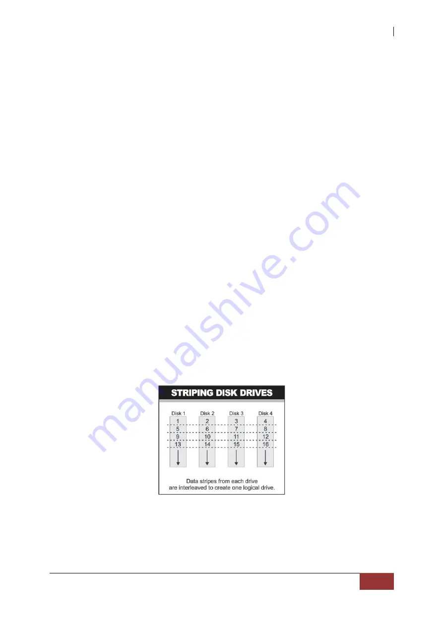


Disk Striping 

Fundamental  to  RAID  technology  is  striping.  This  is  a  method  of  combining  multiple 
drives  into  one  logical  storage  unit.  Striping  partitions  the  storage  space  of  each  drive 
into  stripes,  which  can  be  as  small  as  one  sector  (512  bytes)  or  as  large  as  several 
megabytes.  These  stripes  are  then  interleaved  in  a  rotating  sequence,  so  that  the 
combined space is composed alternately of stripes from each drive. The specific type of 
operating environment determines whether large or small stripes should be used. 
 
Most  operating  systems  today  support  concurrent  disk  I/O  operations  across  multiple 
drives. However, in order to maximize throughput for the disk subsystem, the I/O  load 
must be balanced across all the drives so that each drive can be kept busy as much as 
possible. In a multiple drive system without striping, the disk I/O load is never perfectly 
balanced.  Some  drives  will  contain  data  files  that  are  frequently  accessed  and  some 
drives will rarely be accessed. 


By  striping  the  drives  in  the  array  with  stripes  large  enough  so  that  each  record  falls 
entirely within one stripe, most records can be evenly distributed across all drives. This 
keeps  all  drives  in  the  array busy  during  heavy  load  situations.  This  situation  allows  all 
drives to work concurrently on different I/O operations, and thus maximize the number 
of simultaneous I/O operations that can be performed by the array. 

Summary of Contents for 12G SAS

Page 1: ...12G SAS NAS System Hardware Manual Revision 1 0...

Page 2: ...er 2 Getting Started 11 2 1 Packaging Shipment and Delivery 11 2 2 Unpacking the NAS System 11 2 3 Identifying Parts of the NAS System 12 2 3 1 Front View 12 2 3 1 1 Front Panel Controls and Indicator...

Page 3: ...ght No part of this publication may be reproduced stored in a retrieval system or transmitted in any form or by any means electronic mechanical photocopying recording or otherwise without the prior wr...

Page 4: ...e plugging in any power cords cables and connectors make sure that the power switches are turned off Disconnect first any power connection if the power supply module is being removed from the enclosur...

Page 5: ...and 3 5 hot swappable 12G s SAS 6Gb s SATA hard drives Supports RAID levels 0 1 5 6 10 50 and 60 Support two 10Gb Ethernet ports Supports hot spare and automatic hot rebuild Centralization of Data and...

Page 6: ...re PCIE PCI slot for H W upgrade RAID Controller 1 2GHz dual core RAID on Chip ROC storage processor RAID level RAID 0 1 5 6 10 50 and 60 Supports 1GB DDRIII cache memory Supports hot spare and automa...

Page 7: ...e as several megabytes These stripes are then interleaved in a rotating sequence so that the combined space is composed alternately of stripes from each drive The specific type of operating environmen...

Page 8: ...disk drives that store duplicate data but appear to the computer as a single drive Although striping is not used within a single mirrored drive pair multiple RAID 1 arrays can be striped together to c...

Page 9: ...ID 5 in that data protection is achieved by writing parity information to the physical drives in the array With RAID 6 however two sets of parity data are used These two sets are different and each se...

Page 10: ...ted and written across all the drives RAID 6 provides for an extremely high data fault tolerance and can sustain multiple simultaneous drive failures It is a perfect solution for mission critical appl...

Page 11: ...to the shipping carton may indicate that the contents of the carton are damaged If any damage is found do not remove the components contact the dealer where you purchased the subsystem for further ins...

Page 12: ...NAS System 12 User s Manual 2 3 Identifying Parts of the NAS System The illustrations below identify the various parts of the subsystem 2 3 1 Front View Slot No...

Page 13: ...tem is powered on N A Off System is not powered on 2 System Fail LED Red Solid on System Fault Beeper 3 LAN LED From top to bottom ranked LAN0 LAN3 Orange Blink Link between system and network N A Off...

Page 14: ...r is on and hard drive status is good for this slot N A Off Indicates there is no disk drive in this slot 2 HDD Status LED Green Blink Indicates the disk drive is busy or being accessed Red Solid on I...

Page 15: ...VGA Port Use this to connect a VGA monitor 5 LAN Ports The system comes with two 10Gb Ethernet ports LAN0 and LAN1 6 LAN Port LED Indications There are two LEDs on each LAN port Please refer to the t...

Page 16: ...nection Green Data Activity Green 10Gbps connection On Link 7 SAS Expansion Port For connecting to SAS Expansion Chassis 8 RS232 Port Phone Jack This is used for upgrading the firmware of JBOD Control...

Page 17: ...NAS System User s Manual 17 2 4 Drive Carrier Module The Drive Carrier Module houses a 2 5 inch 3 5 inch hard disk drive...

Page 18: ...of the tray Press the other side of HDD downward to the tray c Turn the disk tray upside down Align the three screw holes of the disk drive in the three Hole 3 5 of the disk tray To secure the disk dr...

Page 19: ...al 19 3 4 and 5 disk 6 disk Three bottom mounting holes of drive Three bottom mounting holes of drive NOTE All the disk tray holes are labelled accordingly Different screw positions Comparing 6 Disk D...

Page 20: ...NAS System 20 User s Manual d Slide the tray into a slot e Close the lever handle until you hear the latch click into place...

Page 21: ...the release button then pull outward on the handle b Place the 2 5 hard drive in the disk tray c Install the mounting screws on the bottom part to secure the drive in the disk tray d Slide the tray in...

Page 22: ...and mouse to the USB to PS 2 converter cable and then connect the USB connector to the USB port on the Server 2 7 Powering On 1 Plug in the two power cords into the AC Power Input Socket of PSU locate...

Reviews: