MVI56-DEM
♦
ControlLogix Platform
Reference
Honeywell DE Communication Module
Page 56 of 80
ProSoft Technology, Inc.
March 6, 2008
5.6
MVI56-DEM Read Block
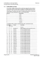
This section contains the format of the read blocks passed from the module to
the processor. Refer to the Reference chapter for a detailed definition of each
parameter. These blocks have block identification codes that determine which
channel data is contained in the block. The following table lists the relationship
between the block identification codes and the channel data:
Block ID
Channel Data
0
1 and 2
1
3 and 4
2
5 and 6
3
7 and 8
4
9 and 10
5
11 and 12
6
13 and 14
7
15 and 16
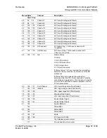
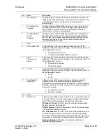
The following table contains a detailed listing of the read block structure:
Words Bytes
Channel
Description
Start
Stop
0 0 1
Reserved
1
2
3
Write Block ID
Block identification code for write block to receive
2
4
7
Channel 1
PV Value (Floating-point format)
4
8
11
Channel 2
PV Value (Floating-point format)
6
12
15
Channel 3
PV Value (Floating-point format)
8
16
19
Channel 4
PV Value (Floating-point format)
10
20
23
Channel 5
PV Value (Floating-point format)
12
24
27
Channel 6
PV Value (Floating-point format)
14
28
31
Channel 7
PV Value (Floating-point format)
16
32
35
Channel 8
PV Value (Floating-point format)
18
36
39
Channel 9
PV Value (Floating-point format)
20
40
43
Channel 10
PV Value (Floating-point format)
22
44
47
Channel 11
PV Value (Floating-point format)
24
48
51
Channel 12
PV Value (Floating-point format)
26
52
55
Channel 13
PV Value (Floating-point format)
28
56
59
Channel 14
PV Value (Floating-point format)
30
60
63
Channel 15
PV Value (Floating-point format)
32
64
67
Channel 16
PV Value (Floating-point format)
34
68
71
Channel 1
SV Value (Floating-point format)
36
72
75
Channel 2
SV Value (Floating-point format)
38
76
79
Channel 3
SV Value (Floating-point format)
40
80
83
Channel 4
SV Value (Floating-point format)
42
84
87
Channel 5
SV Value (Floating-point format)
44
88
91
Channel 6
SV Value (Floating-point format)


