


Operation
Page 45 of 69
4.
OPERATION
4.1.
MESSAGE ROUTING
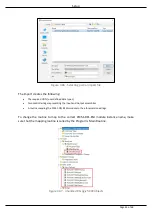
When the PLX51-DF1-MSG has been set up, the DF1 message initiator sends a read/write to
a DF1 address, then routed to a Logix tag. There are various indicators to determine if the
mapping has routed the DF1 messages correctly. Refer to the diagnostics section for a more
detailed explanation.
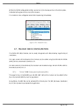
4.2.
RSLOGIX 5000 ASSEMBLIES
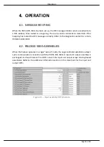
When the module operates in a Logix “owned” mode, the Logix controller establishs a class 1
cyclic communication connection with the PLX51-DF1-MSG. A input and output assembly is
exchanged at a fixed interval. The UDTs convert the input and output arrays into tag-based
assemblies. Refer to the additional information section in this document for the input and
output UDTs.
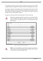
Figure 4.1. – Input assembly UDT structure
Summary of Contents for PLX51-DF1-MSG
Page 1: ...PLX51 DF1 MSG DF1 Messenger DF1 to EtherNet IPTM Messenger December 2017 USER MANUAL...
Page 4: ...Page 4 of 69...
Page 10: ...Page 10 of 69...
Page 48: ...Operation Page 48 of 69...
Page 60: ...Page 60 of 69...
Page 64: ...Page 64 of 69...
Page 68: ...Page 68 of 69...


