background image

MVI56E-AFC / MVI69E-AFC ♦ Enhanced Liquid and Gas Flow Computer 

Configuring Site Parameters 

ControlLogix® and CompactLogix™  

Setup and Configuration Guide 

ProSoft Technology, Inc. 


Page 35 of 151 

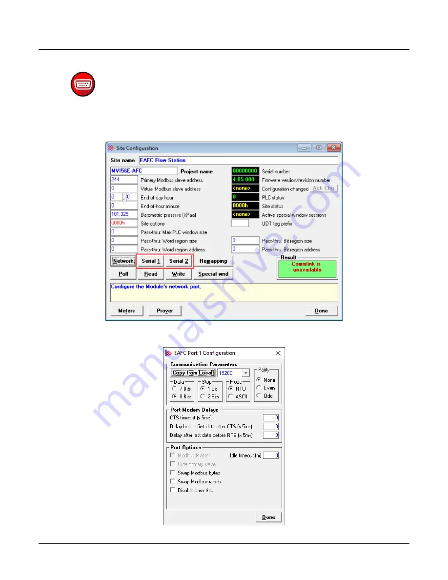
3.6.3  Configuring Serial 1 and Serial 2 


The AFC modules contain two serial port connections. Serial 2 may be used as a 
Modbus Master. To configure the serial port connections, select the 

S

ERIAL 

1

 or 

S

ERIAL 

2

 button in the 

Site Configuration

 dialog.  


This opens the 

EAFC Port Configuration

 dialog. 


Summary of Contents for MVI56E-AFC

Page 1: ...MVI56E AFC MVI69E AFC Enhanced Liquid and Gas Flow Computer ControlLogix and CompactLogix July 14 2021 SETUP AND CONFIGURATION GUIDE ...

Page 2: ...and dimensions may contain technical inaccuracies or typographical errors ProSoft Technology makes no warranty or representation as to its accuracy and assumes no liability for and reserves the right to correct such inaccuracies or errors at any time without notice If you have any suggestions for improvements or amendments or have found errors in this publication please notify us No part of this d...

Page 3: ...PA 70 for installation in the U S or as specified in Section 18 1J2 of the Canadian Electrical Code for installations in Canada and in accordance with the authority having jurisdiction The following warnings must be heeded A Warning Explosion Hazard Substitution of components may impair suitability for Class I Division 2 B Warning Explosion Hazard When in hazardous locations turn off power before ...

Page 4: ...ad 800 mA 5 1 Vdc 3 mA 24 Vdc Operating Temperature 0 C to 60 C 32 F to 140 F Storage Temperature 40 C to 85 C 40 F to 185 F Shock 30 g operational 50 g non operational Vibration 5 g from 10 Hz to 150 Hz Relative Humidity 5 to 95 with no condensation All phase conductor sizes must be at least 1 3 mm2 and all earth ground conductors must be at least 4mm2 CompactLogix Backplane Current Load 500 mA 5...

Page 5: ...5 2 Accessing and Using the Modbus Dictionary 15 2 Creating an EAFC Manager Project 19 2 1 Creating the Project 19 2 2 Setting Project Preferences 19 3 Configuring Site Parameters 21 3 1 Accessing Site Configuration Parameters 21 3 2 Configuring Site Options 24 3 3 Configuring Pass Thru Options 24 3 4 Viewing Site Configuration Status 25 3 5 UDT Tag Prefix 26 3 6 Configuring Communication Paramete...

Page 6: ...etting Accumulators and Flow Rates 61 6 3 1 Flow Rate Period Unit 61 6 3 2 Flow Rate Unit 62 6 3 3 Accumulation Unit 63 6 3 4 Accumulator Rollover 63 6 4 Configuring Process Input Scaling 64 6 4 1 Zero Scale 64 6 4 2 Full Scale 64 6 5 Enabling Disabling the Meter Control Opts 65 6 6 Configuring Calculation Options 66 6 7 Configuring Resettable Accumulators 66 6 7 1 Non Resettable Accumulators 67 6...

Page 7: ...t Connection 101 17 2 Serial Connection 102 18 Downloading the Project to the Module 105 19 Backplane Return 107 19 1 About Backplane Return 107 19 2 Process Input Function Block 107 19 3 Component Analysis Function Block 107 19 4 Configuring the Backplane Return Function Blocks 108 19 5 Backplane Return Configuration 110 19 6 Importing a Backplane Return UDT 111 19 7 Copying the Backplane Return ...

Page 8: ...irmware Upgrade Link 130 22 2 Component Integrity Link 130 22 2 1 Software Component Detail Information 131 22 2 2 Component Integrity Page Operation 132 22 2 3 Verification 133 22 3 Monitor 133 22 3 1 Site Configuration 136 22 3 2 Meter Configuration 137 22 3 3 Stream Configuration 140 22 3 4 Meter Calculations 141 22 3 5 Meter Accumulators 143 22 3 6 Meter Status 143 22 3 7 Data Displays 146 23 ...

Page 9: ...E AFC web page 2 Click on the DOWNLOADS tab 3 Click on the PROSOFT EAFC MANAGER link and follow the prompts to download and install the application 1 1 2 Downloading AOIs 1 Navigate to the appropriate MVI56E AFC or MVI69E AFC web page 2 Click on the DOWNLOADS tab 3 Select MVI56E AFC or MVI69E AFC ADD ON INSTRUCTIONS link The AOIs are downloaded as a zip file The zip file contains the Main AOI as w...

Page 10: ...tions apply only to particular types To locate configuration information specific to your meter refer to the following table What type of meter are you configuring What is the primary output from your flow meter and associated instrumentation Configure the metering principle as See the following sections of this guide Orifice Meter Differential Pressure Differential pressure Configuring Differenti...

Page 11: ...Frequency Options on page 84 Ultrasonic Meter Flow Rate Flow rate Configuring Differential Meter Parameters on page 79 Pulse Count and Pulse Frequency Pulse count Configuring Linear Meter Pulse Count Options on page 82 Pulse Frequency Only Pulse frequency Configuring Linear Meter Pulse Frequency Options on page 84 Turbine Meter Flow Rate Flow rate Configuring Differential Meter Parameters on page ...

Page 12: ...uide ProSoft Technology Inc Page 12 of 151 What type of meter are you configuring What is the primary output from your flow meter and associated instrumentation Configure the metering principle as See the following sections of this guide Pulse Frequency Only Pulse frequency Configuring Linear Meter Pulse Frequency Options on page 84 ...

Page 13: ...owing icons to assist you during configuration Accumulator Alarm Back Calculate Calibrate Calibrate 2 Ethernet Event Export Flow Gas Liquid Login Logout Meter Meter Network Delete Permission Add Permission Edit Permission Generic Permission Port Pressure Prover Pulse Delete Role Add Role Edit Role Generic Role Serial Connection Site Stream Temp User Delete User Add User Edit User View Delete View ...

Page 14: ...n registers and dictionary sections It is recommended that you use the Modbus Dictionary to locate bank and register values to ensure that you are looking at the latest information 1 5 1 About the Modbus Dictionary The Modbus dictionary PROJECT MODBUS DICTIONARY provides a means to locate data anywhere in the module The dictionary allows you to select various data types from database regions It th...

Page 15: ...d paying attention to its version This ensures that the dictionary items present for your module are available for display 1 In EAFC Manger from the PROJECT tab select MODBUS DICTIONARY The Modbus Dictionary displays 3 In the Source Configuration area select Local if you are running the dictionary locally or On line if you are connected to the module 4 Select the Dictionary Section from the dropdo...

Page 16: ...nd CompactLogix Setup and Configuration Guide ProSoft Technology Inc Page 16 of 151 5 Select the METER stream Information will be displayed only for the selected meter 6 Check the SHOW BITS checkbox to enable the display of individual bits in the Bank Reg column 7 Click on the appropriate row ...

Page 17: ...ogix Setup and Configuration Guide ProSoft Technology Inc Page 17 of 151 Tip The Search box allows you to search for specific data The search is applied to entries in the Description column and is not case sensitive 8 Once a row is selected additional information is displayed at the bottom of the window ...

Page 18: ...s In the first row the first position indicates whether the register is a Holding Register H or an Input Register I the second position represents the register 8000 The third position indicates high order bytes H low order bytes L multiple registers and a plus sign indicates that there are two registers used for 32 bit quantities i e long integer and floating point elements If SHOW BITS is checked...

Page 19: ...1 2 Creating an EAFC Manager Project 2 1 Creating the Project 1 From your PC Laptop run the EAFC Manager software 2 Select FILE NEW MVI56E AFC or MVI69E AFC MVIXXE AFC XX METERS VX XX Communication between the EAFC Manger and the AFC module is not required during the configuration stage 2 2 Setting Project Preferences 1 From the FILE menu select PREFERENCES The Preferences dialog displays ...

Page 20: ...e represented in the Stream Component Analysis dialog Options are as follows Percent Fraction Show density of gas relative to that of air as This setting determines which term is used to indicate the density of gas relative to that of air in EAFC Manager Options are as follows Specific gravity Relative density Auto report transmitter calibration on close session To report a transmitter calibration...

Page 21: ...ters The EAFC Manager Site Configuration dialog box allows you to assign the following project settings Project name Modbus slave addresses Memory allocation Port configuration and mapping Site options and status You can also obtain the EAFC firmware version from this window 3 1 Accessing Site Configuration Parameters From the Project menu choose SITE CONFIGURATION This opens the Site Configuratio...

Page 22: ...ts the minute of the day when the daily archives are created The default value of 0 zero creates the daily archive at midnight The entry format is hh mm where hh represents hour and mm represents minute of the hour Valid values for hour are between 0 and 23 Valid values for minute of the hour are between 0 and 59 The entered hour and minute of the hour values are converted to end of day minute val...

Page 23: ...ing Site Configuration Status on page 25 for details UDT tag prefix This field shows the prefix used for generated UDT names See UDT Tag Prefix on page 26 for details Network Click thiis button to configure Modbus TCP IP See Configuring Modbus TCP IP on page 26 for details Serial 1 and Serial 2 Click these buttons to configure the two serial port connections See Configuring Serial 1 and Serial 2 o...

Page 24: ...ed events then the log is locked Controllable events changes to most datum points are not allowed to occur Non critical non controllable events e g checksum alarms are discarded and are permanently lost and critical non controllable events e g PLC mode change are written as usual and the overwritten never downloaded events are permanently lost A locked log must be downloaded to unlock it for norma...

Page 25: ...s Thru feature for write commands When the pass thru region in the virtual slave is properly configured all Modbus write commands pointing inside that area will be handled by ladder logic using the Modbus Pass Thru function block 3 4 Viewing Site Configuration Status This section of the Site Configuration dialog box is used to provide Site status information Site status features are discussed in t...

Page 26: ...ated for other AFC modules in the same rack you can enter an optional prefix in the UDT Tag Prefix field The prefix must be an alphanumeric string of not more than 3 characters This string will be prepended to each generated name after the leading MVIxxE AFC with an underscore _ separator If you do not specify a UDT tag prefix generated names are not prefixed 3 6 Configuring Communication Paramete...

Page 27: ...E and POLL buttons of the Site Configuration dialog if a connection does not already exist You must then enter the appropriate port settings and establish a connection before proceeding If a connection is already present the Local Port Settings dialog displays only when you access it from the COMMUNICATIONS menu Similarly if the connection exists but the operator has not logged in while the other ...

Page 28: ...olLogix and CompactLogix Setup and Configuration Guide ProSoft Technology Inc Page 28 of 151 3 6 2 Configuring Modbus TCP IP To configure the Modbus TCP IP parameters for the Ethernet port select the NETWORK button in the Site Configuration dialog This opens the AFC Network Configuration dialog ...

Page 29: ...guration The Server tabs in the AFC Network Configuration dialog allow you set different configurations for up to four servers 1 Click on the tab of the server that you want to configure 2 Enable the server by selecting the ENABLE checkbox 3 In the Network Interface area enter the IP address of the physical interface inconfigure the network interface 4 Set up Mode and AFC Slave settings Modbus TCP...

Page 30: ...ts own Modbus database the unit code is ignored and is echoed verbatim in the response regardless of its value If set to Gateway protocol converter between the TCP network on one end and a traditional serial Modbus network on the other end the serial Modbus network is virtual consisting of the modules primary and virtual slaves only and the unit code must be the configured slave address of the tar...

Page 31: ...required For example each server might represent a different network Server 1 might have a single connection while server 2 may have 3 server 3 with 2 and server 4 with 2 for a total of 8 Reserved connections A reserved connection is one whose resources are always available for use by this server whether or not such a connection is currently in use so that regardless of activity on other servers t...

Page 32: ...h comprises An IP range network IP and mask length A true or false disposition flag true allow false deny An entry whose components are all zero IP 0 0 0 0 prefix length is 0 disposition is false is empty It is ignored during application of the whitelist and its position in the sequence is irrelevant The relative positioning of non empty entries is relevant however as a later entry can override th...

Page 33: ...etween each A probe is a TCP IP packet that asks the client Are you still there If the client answers any probe with Yes I m still here then the connection is good The client is merely silent and the server resets keepalive logic for another cycle If the client does not answer any probe then the server deems the connection to be broken and closes it to free up its resources for allocation Keepaliv...

Page 34: ...ge of protocol e g gateway vs end device mode swap options Creating orphans of a connection breaks the association between the connection and its parent server so that the connection no longer belongs to any server Server settings in effect prior to orphan creation become frozen for that orphan for the remainder of its limited life A subsequent reconfiguration of this or any other server that rees...

Page 35: ...tion Guide ProSoft Technology Inc Page 35 of 151 3 6 3 Configuring Serial 1 and Serial 2 The AFC modules contain two serial port connections Serial 2 may be used as a Modbus Master To configure the serial port connections select the SERIAL 1 or SERIAL 2 button in the Site Configuration dialog This opens the EAFC Port Configuration dialog ...

Page 36: ...s after transmitter receipt of clear to send frame before transmitting data frame Delay after last data before RTS x 5ms Delay period x 5ms after transmitter sends last data frame before sending request to send frame to receiver for next message Port Options Option Description Modbus Master Enables the Modbus Master for the port Serial 2 The Modbus Master command is generated from the processor us...

Page 37: ...Swap Modbus Bytes If checked the bytes transferred by a Modbus master device will be swapped Swap Modbus Words If checked the words transferred by a Modbus master device will be swapped This setting only applies to double register data items floating point and long integer Disable Pass thru The Modbus pass through feature allows you to configure a Modbus Pass through region in the virtual slave Pr...

Page 38: ...ng Site Parameters ControlLogix and CompactLogix Setup and Configuration Guide ProSoft Technology Inc Page 38 of 151 3 7 Poll Button The POLL button updates the display of site status the black background boxes in the upper right quadrant of the Site Configuration dialog ...

Page 39: ...nc Page 39 of 151 3 8 Read Button The READ button reads the current site configuration from the module to the local PC Look at the result area green rectangle on the Site Configuration dialog box for the status of the read operation When a Success indication appears in the result area it indicates that the site configuration has been successfully read to the local PC ...

Page 40: ... on the local PC using EAFC Manager click the WRITE button to transfer the configuration to the module When the Result area shows Success the site configuration has been successfully written to the module After writing the configuration to the module you can click the READ button to read the current module site configuration The configuration should match the last write operation data If the Resul...

Page 41: ...ctivity has occurred within that time period the Event Log activity is abandoned and no data is logged or committed The same holds true for the alarm log transmitter calibration and Enron access You must enter the time interval and the optional Virtual Slave location of the data When you are satisfied with your settings click DONE You can come back at any time and change your settings If you want ...

Page 42: ...ou provide to EAFC Manager Configuring a meter consists of the following steps 1 Configure the meter and stream identification parameters For details see section 4 2 Configuring Meter and Stream Identification Parameters on page 43 2 Configure the meter classification parameters These include Product Group System of Units Metering Principle and Group Membership For more information see section 4 4...

Page 43: ... Guide ProSoft Technology Inc Page 43 of 151 4 2 Configuring Meter and Stream Identification Parameters 4 2 1 Setting Meter Identification Parameters The Identification Parameters identify the meter 1 Select the Meter number 2 Click the IDENTIFICATION button in the Meter area of the dialog upper part to display the Meter Identification window ...

Page 44: ...et Tag General Type Manufacturer Model Serial Number Size Nominal K Factor 4 Click OK when complete Repeat this for every configured meter 4 2 2 Setting a Stream Name 1 To set a Stream Name click on the IDENTIFICATION button under the Stream Enabled indicator 2 Enter a product description and click OK 4 3 Setting End of Period Parameters These parameters set the End of day hour and End of hour min...

Page 45: ...9 before being written to the module This moment is relative to the module s wallclock which is expected to be UTC time 4 3 2 End of hour minute This parameter sets the minute of the hour when the hourly archives are created The default value of 0 zero creates hourly archives at the top of each hour Valid values are between 0 and 59 4 3 3 Setting Precedence Global settings for End of day hour and ...

Page 46: ...t you select here affects the available parameters that must be configured for your application EAFC Manager needs these parameters in order to hide or show parameters that pertain specifically to your meter and its primary output based on your meter and associated instrumentation 4 4 1 Product Group The Product Group represents what you are measuring i e gas or liquid The Product Group dropdown l...

Page 47: ...ased on the type of meter and its primary output What type of meter are you configuring What is the primary output from your flow meter and associated instrumentation Configure the metering principle as Orifice Meter Differential Pressure Differential pressure V Cone Meter Differential Pressure Differential pressure Wedge Meter Differential Pressure Differential pressure Coriolis Meter Flow Rate F...

Page 48: ...a member of a meter group parent or a standalone autonomous meter channel When 0 not a member of a meter group parent the meter is a standalone autonomous meter channel When the Group membership value is a number from 1 to 16 the meter is a member of a meter group parent Note If you assign the meter to a group information and parameters that are sourced from the meter group parent are disabled For...

Page 49: ...in configuration parameters must be consistent for all members while other member configuration parameters may be configured independently for each member We use the following terms to refer to these two categories of parameters Group Member Synchronization refers to configuration parameters that are sourced from the meter group parent s configuration parameters Group Parent Not Applicable refers ...

Page 50: ... written to a group member these points behave as if the meter were autonomous fully independent from other meters When such a parameter is written to a group parent however the change attempt is denied by overwriting the request with the original before verification exactly the same technique as denying changes to Group Member Full Propagation points of group member meters An example of a Group P...

Page 51: ...eter is written to a group member the change attempt is denied by overwriting the requested data with the original before verifying the request just as if the point had been written with no change requested the member can be updated only by writing the change to its parent An example of a Group Member Synchronization configuration parameters are the meter reference conditions both reference temper...

Page 52: ...meter channel is a group parent this bit field is interpreted as a binary value 0 If the meter channel is a group member this bit field is the 1 based index of the meter channel that is configured as this member s parent If the meter channel is autonomous performing measurement associated with a physical meter but not related with or to any meter group then this bit field has value 0 Meter Group R...

Page 53: ...in the value for holding register 8028 as shown in the following screen capture The hexadecimal value of the register is 8002 which is 1000 0000 0000 0010 in binary The Meter group relationship data point position 15 has a value of 1 indicating that the meter has a relationship to a meter group The Group parent meter channel data point positions 10 14 has a value of 0 indicating that Meter 1 is th...

Page 54: ...arent 5 2 Configuring the Meter Group Parent This selection configures the meter channel as a group parent There is no physical metering device directly associated with the channel Instead the function of the channel is to summarize the results of other group member channels that do have associated physical metering devices and perform the actual measurement Note The meter group parent must be con...

Page 55: ...s of these parameters see section 4 4 Configuring Meter Classification Parameters on page 46 Note The meter group parent and group members must have the same product group 3 If you selected Gas for the product group set up the gas component analysis configuration See the AFC Reference Guide for more information 4 From the Metering principle dropdown list select Meter group parent 5 Write the confi...

Page 56: ...med as so by the adjacent label and if non zero indicates a group member meter and textually confirmed as so by the adjacent label reading Member of group and is the 1 based number of the group parent which itself has its Metering principle dropdown configured as Meter group parent Note The meter group parent must be configured prior to the members of the group To configure meter group members 1 F...

Page 57: ...parent enter the 1 based meter number of the group parent The text Member of group will appear in blue next to the field Note If the parent was not configured before the member the text member of group will appear in red to indicate an error Red text will also appear if the member is not of the same product group and system of units as the parent 5 Write the configuration to the module by selectin...

Page 58: ...e ProSoft Technology Inc Page 58 of 151 6 Configuring Common Parameters The Common parameters in the Meter Configuration dialog box must be configured for all projects Common parameters include Physical Device Reference Conditions Accumulators and Flow Rates Process Input Control Options Backplane Return Calculation Options Resettable Accumulators ...

Page 59: ...calculation methods based on the meter If you are using a differential gas type principle measuring differential pressure you have the option of selecting from the following standards Orifice plate AGA 3 2012 Orifice plate AGA 3 1992 Orifice plate ISO 5167 2 Nozzle ISA 1932 ISO 5167 3 type 1 Nozzle long radius ISO 5167 3 type 2 Nozzle Venturi ISO 5167 3 type 3 Venturi tube cast ISO 5167 4 type 1 V...

Page 60: ... Temperature and Pressure Measurements of gas and liquids are calculated based on their characteristics at a specific temperature and atmospheric pressure Specify the reference conditions in the Reference Conditions area The default values are 15 C 101 325 kPaa SI and 60 F 14 696psia US which are the standard API base conditions If the configured reference conditions are different from API base th...

Page 61: ...nfiguring Common Parameters ControlLogix and CompactLogix Setup and Configuration Guide ProSoft Technology Inc Page 61 of 151 6 3 Setting Accumulators and Flow Rates 6 3 1 Flow Rate Period Unit Click on the FLOW RATE PERIOD UNIT box to change the flow rate period ...

Page 62: ...uid and Gas Flow Computer Configuring Common Parameters ControlLogix and CompactLogix Setup and Configuration Guide ProSoft Technology Inc Page 62 of 151 6 3 2 Flow Rate Unit Click on the FLOW RATE UNIT box to change the flow rate unit ...

Page 63: ...x to change volume accumulator units 6 3 4 Accumulator Rollover This is the value when mass accumulators are reset to zero and it is 1 greater than the highest value that the accumulator may hold A value of 1000000 specifies a 6 digit accumulator that rolls over to 0 from 999999 Any unsigned 32 bit value may be entered A value of 0 indicates a free running accumulator which rolls over to 0 from 42...

Page 64: ... the alarm bit for the meter is set For a list of acceptable ranges for the parameters displayed in the Process Input Scaling dialog see the AFC Reference Guide The entries available on this dialog box depend on the selected product group device and primary input Product Group Input Variables Gas Temperature Pressure Flow Rate Differential Pressure Pulse Frequency Liquid Temperature Pressure Flow ...

Page 65: ...ble the meter by unchecking this box before you can change the meter type or product group You should also disable any meter that is not being used to allow for best possible module performance After enabling or disabling the meter click DONE and then click the WRITE button in the Meter Configuration area To retrieve the status of a meter click the READ button in the Meter Configuration area Note ...

Page 66: ...on to access the Meter Calculations Options dialog Details on each option can be found in the Modbus Dictionary Options that to not apply to the current application are grayed out See Calculations Options in the AFC Reference Guide for detailed information 6 7 Configuring Resettable Accumulators The AFC modules support a total of 12 accumulators per meter channel divided into the following categor...

Page 67: ...pplied both to the meter accumulators and to the accumulators for the active stream 6 7 1 Non Resettable Accumulators The non resettable accumulators are only reset when the accumulator rollover value is reached The accumulator rollover value and the accumulator unit must be configured using the EAFC Manager The module supports six non resettable accumulators in order to show the measured quantity...

Page 68: ... for these registers 6 7 2 Resettable Accumulators From the Resettable Accumulator Select window click OPTIONS The resettable accumulators are referred to as Resettable Accumulator 1 Resettable Accumulator 2 Resettable Accumulator 3 Resettable Accumulator 4 Resettable Accumulators are configured from the Resettable Accumulator Select dialog box To open this dialog box click the RESETTABLE ACCUM bu...

Page 69: ... Gross code 4 Resettable accumulator 3 128 Gross Standard code 5 Resettable accumulator 4 129 Mass code 1 Valid Configuration Codes The valid configuration codes are Code Quantity 0 None 1 Mass 2 Energy Gas Only 3 Net 4 Gross 5 Gross Standard Liquid Only 6 Water Liquid Applications Only For example moving a value of 4 to holding register 8126 will configure Meter 1 s resettable accumulator 1 as Gr...

Page 70: ...cumulators using the Meter Monitor dialog in EAFC Manager Resetting from Ladder Logic The ladder logic may send a meter signals block to command one or more resettable accumulators to be reset This feature is especially important for applications involving field installations that require shipping and or receiving product batches of predetermined size Refer to the Ladder Logic section of the AFC R...

Page 71: ... more information on configuring and monitoring events Resetting when the Accumulator Rollover Value is reached The resettable accumulator is reset when the accumulator rollover value is reached You must configure the accumulator rollover value using the EAFC Manager Meter Configuration Resetting a resettable accumulator applies to that accumulator for both the meter and for all its streams Archiv...

Page 72: ...ulator Calculation The Net Accumulator Calculation depends on the product group gas or liquid For gas applications the Net Accumulator is calculated as follows Converts to Reference Temperature and Pressure Gross Accumulator Net Accumulator For liquid applications all except Emulsion the Net Accumulator is calculated as follows Converts to Reference Temperature and Pressure Subtracts Water Gross A...

Page 73: ...ccumulation of a wide range of increments while keeping a high precision of fractional part with an approximately constant and small round off error The totalizer stores the integral part of an accumulator as a 32 bit unsigned integer The residue is the fractional part always less than 1 0 expressed as a 32 bit IEEE floating point The Total Accumulator value is given by the formula ACCUMULATOR TOT...

Page 74: ...ect For more information see the other three Alarming meter control alarms the Acknowledgement required registers and the Meter alarms registers themselves Alarming Disallow pre acknowledge If set the acknowledgement of any alarm requires the alarm condition to have been resolved and its corresponding bit in the Meter alarms registers to be clear If clear then alarm acknowledgement may be performe...

Page 75: ...hat occurs consequent to an alarm e g value substitution separate accumulation persists until both the alarm condition has disappeared and the alarm has been acknowledged at which time normal measurement is resumed If clear normal measurement is resumed when the alarm condition has disappeared regardless of whether or not the alarm has been acknowledged This option causes value substitution persis...

Page 76: ...stream via a Modbus transaction Enabling a stream allows it to become active and disabling it prevents it from becoming active The currently active stream may not be disabled As the physical switching of a product stream through a meter is almost always accompanied by additional actions such as changing the position of valves it is expected that the stream switching transaction will be issued by t...

Page 77: ...efault heating value volumetric by selecting the Volumetric checkbox in the Stream Component Analysis dialog Use meter factor to full precision non Standard If Use meter factor to full precision is clear the Meter Factor is rounded to four decimal places before being used to calculate gross volume gross pulses KF MF If the option is set the MF is used as is without rounding Rounding applies only t...

Page 78: ......

Page 79: ...Technology Inc Page 79 of 151 7 Configuring Differential Meter Parameters If you are using a differential meter select either Differential Pressure or Flow Rate as the metering principle If you select Differential Pressure as the metering principle you must configure the following parameters You must also click on the ORIFICE button in order to specify orifice geometry ...

Page 80: ...Discharge a multiplicative factor used in calculating the flow rate For a V cone meter there is no corresponding calculation so the Coefficient of Discharge must be entered from the manufacturer s data sheet The V Cone Discharge Coefficient has no meaning unless the V Cone Device option is selected see Calculation Options button Viscosity The viscosity of the fluid used only in the calculation of ...

Page 81: ...ompactLogix Setup and Configuration Guide ProSoft Technology Inc Page 81 of 151 If you select Flow Rate as the metering principle you must configure the following parameter FR Flow Threshold If at any time the flow rate value is less than the FR Flow Threshold parameter the module will treat the flow rate as zero no flow ...

Page 82: ...e This parameter sets the value at which the pulse count will rollover to zero It is essential that this value match the actual pulse rollover used in the field by the pulse meter or counter module otherwise the flow calculation will generate unexpected values Enter this value as maximum value 1 Master pulse count rollover This is a value that is 1 greater than the highest value that master pulse ...

Page 83: ...MVI69E AFC Enhanced Liquid and Gas Flow Computer Configuring Linear Meter Pulse Count Options ControlLogix and CompactLogix Setup and Configuration Guide ProSoft Technology Inc Page 83 of 151 Parameter Description ...

Page 84: ... pulse frequency Values can range between 0 and 1 0e 06 Hz The default is 0 0 Master pulse count rollover This is a value that is 1 greater than the highest value that master frequency counters will contain Enter 0 for free running counters which rollover to 0 from 4294967295 K factor This is the expected number of pulses expected per unit of fluid passing through a flow meter Values can range bet...

Page 85: ... Default specific gravity or Default relative density Normally the AFC modules use the Detail Characterization Method of the AGA 8 standard to calculate the density of the gas from its composition as given by the molar analysis The density is used in all subsequent calculations When AGA 8 cannot be applied because no analysis is available no components selected or analysis is all zero then this va...

Page 86: ...erating conditions to be substituted for the output of AGA 8 Default heating value Typically the AFC modules use the Detail Characterization Method of the AGA 8 standard to calculate the heating value of the gas from its composition as given by the molar analysis The heating value is used in all subsequent calculations When AGA 8 cannot be applied because no analysis is available no components sel...

Page 87: ... Specific Gravity or Default Relative Density You can override the default specific gravity or default relative density and suppy your own calculated value for this field 1 From the Meter Configuration dialog select ANALYSIS If you have not already selected the components to include in the analysis the Analysis Configuration dialog displays If this is the case make the appropriate selections and t...

Page 88: ... Configuration Guide ProSoft Technology Inc Page 88 of 151 The Stream Component Analysis dialog displays 2 Click the Calc dropdown to the right of the Relative density or Specific gravity field and select OVERRIDE 3 In the Specific gravity or Relative density field enter the new value for the default heating value 4 Click DONE ...

Page 89: ...f 151 10 3 Override the Default Heating Value You can override the default heating value and suppy your own calculated value for this field 1 From the Meter Configuration dialog select ANALYSIS If you have not already selected the components to include in the analysis the Analysis Configuration dialog displays If this is the case make the appropriate selections and then click OK ...

Page 90: ... CompactLogix Setup and Configuration Guide ProSoft Technology Inc Page 90 of 151 The Stream Component Analysis dialog displays 2 Click the Calc dropdown to the right of the Heating value field and select OVERRIDE 3 In the Heating value field enter the new value for the default heating value 4 Click DONE ...

Page 91: ...de ProSoft Technology Inc Page 91 of 151 11 Configuring Liquid Parameters 11 1 About the Liquid Parameters The liquid parameters display in the Liquid area of the Meter Configuration dialog when the Product group field is set to a liquid group Following are descriptions of the liquid parameters Some of these display only for certain product groups ...

Page 92: ...if Product group is set to Special applications The units displayed here depend on the value selected in the System of units list Water salinity Salinity of the water This parameter is visible only if Product group is set to Oil wtr emulsions Crd Oil wtr emulsions NGR or Produced injected water 11 2 Liquid Parameter Requirements The following parameters describe requirements for the parameters Par...

Page 93: ... be expressed using any of the following units Units Abbreviation kilograms per cubic meter kg m3 relative density at 60 F Rd 60 API gravity API grams per cubic centimeter g cc 12 2 Setting the Density Units To set the density units select one of the options from the Density units dropdown list in the Meter Configuration dialog The selected units will be used for density values throughout EAFC Man...

Page 94: ...traditional orifice this value is fixed and cannot be changed For a linear pulse meter it characterizes the K factor For a traditional pulse meter such as a turbine this quantity is Gross Volume Flow input unit This value specifies the engineering units base and scaling of the measured quantity selected for the primary input For some meter types for example a traditional orifice this value is fixe...

Page 95: ...chnology Inc Page 95 of 151 14 Configuring K factor Characteristics The K factor Characteristics area of the Meter Configuration dialog is visible when the metering principle is either Pulse Frequency or Pulse Count Click the Measured quantity field to choose the quantity type for this meter Click the Flow input unit field to choose the flow input unit for this meter ...

Page 96: ...asured quantity For a linear pulse meter Gross volume pulses K factor x meter factor The K factor is a factor that converts raw pulse count from the Pulse Meter to a volume and is expressed as Pulses per unit volume such as 1000 pulses per gallon or 3578 224 pulses per cubic meter This number found on the manufacturer s datasheet for the meter is determined at the factory for the specific unit bef...

Page 97: ...ed the meter factor and is a number very close to 1 The procedure that is periodically performed to determine a new meter factor is called proving A pulse type meter is proved periodically to ensure that the meter performs as expected over a period of time A prover passes a known volume of product through the meter and compares the volume indicated by the meter against the fixed volume of the prov...

Page 98: ...onditions Since flow rate depends on the meter factor according to API but meter factor depends on flow rate according to the linearization table the AFC module performs a second iteration of the interpolation in order to obtain an accurate meter factor In the Meter Factor Linearization Curve dialog box click the READ button to transfer the current Meter Factor Linearization configuration from the...

Page 99: ... The flow rates corresponding to non zero meter factors are all different You do not need to enter factor flowrate pairs in any particular order or even enter them all as a contiguous group You may enter each factor flowrate pair into any of the five table entries and the AFC module will sort it If you do not want to enter meter factor linearization data then populate only one entry leaving the ot...

Page 100: ...ning When you insert or remove the module while backplane power is on an electrical arc can occur This could cause an explosion in hazardous location installations Verify that power is removed or the area is non hazardous before proceeding Repeated electrical arcing causes excessive wear to contacts on both the module and its mating connector Worn contacts may create electrical resistance that can...

Page 101: ... Manager Note The following example shows the MVI56E AFC module Connecting the MVI69E AFC module is done in a similar fashion There are two ways to connect the EAFC Manager running on a PC to the AFC Module by Ethernet or Serial The top port eth0 is used to create Ethernet connections Serial 1 and Serial 2 are both available for serial connections 17 1 Ethernet Connection Connect one end of an Eth...

Page 102: ...es how to connect your PC to one of the serial ports on the module 1 Connect the DB 9 adapter to a serial port of the AFC module P1 or P2 2 Connect the null modem cable to the DB 9 adapter cable Connect these to an available serial port on your PC Note Some desktop and notebook computers are not equipped with a serial port In this case you may require a USB to Serial adapter cable with drivers Not...

Page 103: ... Flow Computer Connecting the AFC Module to the EAFC Manager ControlLogix and CompactLogix Setup and Configuration Guide ProSoft Technology Inc Page 103 of 151 The null modem cable that is supplied with the module uses the following cabling scheme ...

Page 104: ...ect the port settings at COMMUNICATIONS LOCAL PORT SETTINGS The default serial communication settings are shown in the following illustration 4 The EAFC Manager will establish communications with the module Open the Project menu and then select SITE CONFIGURATION to open the Site Configuration dialog box 5 On the Site Configuration dialog box click the READ button You should see the word Success i...

Page 105: ...105 of 151 18 Downloading the Project to the Module Note This section use the MVI56E AFC module as an example The MVI69E AFC download process is performed the same way 1 In EAFC Manager select PROJECT DOWNLOAD PROJECT This action opens the Local Port Settings window If you are downloading via the network click TCP IP 2 If you are downloading through one of the serial ports click SERIAL ...

Page 106: ... When the file transfer is complete the following window is displayed Troubleshooting Tip If the EAFC Manager displays an Illegal Data Value message it typically indicates an invalid meter type or product group configuration or the W M switch on the front of the module is in the locked position The module does not accept a configuration file that attempts to change a meter type or product group fo...

Page 107: ...n export the data points as a UDT file that you can then import into RSLogix to allow for viewing the data via controller tags 19 2 Process Input Function Block The Process Input function block is configured by default to deliver process inputs used for measurement These include values that would likely be required by the PLC program on a regular basis This function block is delivered repeatedly a...

Page 108: ...nfiguration dialog shows the database points that were preselected for the Process Input return and the empty mapping for the Component Analysis return You can modify these by selecting desired values from the Modbus database The module will deliver the selected items to the PLC automatically and on a regular basis without requiring you to create and issue a separate backplane transaction such as ...

Page 109: ...the Process Inputs or Component Analysis function block 1 From the Meter Configuration dialog select BACKPLANE RETURN The Backplane Return Configuration dialog displays 2 In the left side of the dialog select the Process Input or Component Analysis tab 3 From the Dictionary section select the dictionary items you wish to include in the function block This activates the INSERT ITEM button ...

Page 110: ...sub directory of the directory that contains the project The directory is named using the name of the project and extension PLC You can import this file into RSLogix by following the instructions in section 19 6 Importing a Backplane Return UDT on page 111 7 Click OK The backplane return function block will be delivered to the PLC 19 5 Backplane Return Configuration The following screen capture il...

Page 111: ...troller Organizer navigate to DATA TYPES USER DEFINED 2 Right click on USER DEFINED 3 Select IMPORT DATA TYPE 4 In the Import Data Type window select the UDT L5X file to import 5 Select IMPORT 6 Click OK to import the UDT 19 7 Copying the Backplane Return Data 1 Create a unique tag of the imported data type 2 Use a COP Copy instruction with the Source as the first element of the meter BackplaneRet...

Page 112: ...turn ControlLogix and CompactLogix Setup and Configuration Guide ProSoft Technology Inc Page 112 of 151 Process Input data is obtained when every process input block is sent to the AFC module The Backplane Return Component Analysis data must be triggered in order to view it ...

Page 113: ...the Archive Files EAFC Manager archives selected meter data on a daily and hourly basis according to the End of day hour and End of hour minute settings This chapter explains how to configure the layout of the archive files and export the data tags as a UDT file for use in RSLogix 20 2 Configuring the Archive Files 1 From the Meter Configuration dialog box select the meter number 2 Click on the AR...

Page 114: ... in the list 7 When you have finished adding dictionary items click the EXPORT UDT button The files are placed in a sub directory of the directory that contains the project The directory is named using the name of the project and extension PLC You can import this file into RSLogix by following the instructions in section 20 3 Importing an Archive Configuration UDT on page 114 20 3 Importing an Arc...

Page 115: ...type 2 Use a COP Copy instruction with the Source as the first element of the meter Archive Fetch xxx Raw data The Dest Destination is a newly created tag of the imported data type The Length is 1 3 Make sure that the data type you are using matches the data that you want to view For example if you want process data ensure that the imported data is actually process data 20 5 Viewing Archive Data N...

Page 116: ...Logix Setup and Configuration Guide ProSoft Technology Inc Page 116 of 151 Archive data must be triggered with the desired age in order to view it For more information on viewing archive data see the ProSoft Technical Note titled How to Fetch Daily and Hourly Archives available at www prosoft technology com ...

Page 117: ... Project and Importing an AOI Note This section use the MVI56E AFC module for examples The MVI69E AFC module is configured like the MVI56E AFC 21 1 Creating an MVI56E AFC RSLogix Project 1 Create a new RSLogix Studio 5000 project 2 In the Controller Organization window expand the I O Configuration folder 3 Select 1756 Backplane and then click the right mouse button to open a shortcut menu 4 On the...

Page 118: ...figuration Guide ProSoft Technology Inc Page 118 of 151 5 On the Select Module dialog box select 1756 MODULE 6 Create a new 1756 MODULE I O Configuration with the following settings Name MVI56EAFC Comm Format Data INT Input Assembly Instance 1 Input Assembly Size 250 Output Assembly Instance 2 Output Assembly Size 248 Configuration Assembly Instance 4 ...

Page 119: ... 119 of 151 7 Adjust the Slot and RPI settings for your application 5ms is the recommended default RPI time do not use an RPI setting below 5ms Click OK to confirm 8 The MVI56E AFC module is now visible in the I O Configuration folder 21 2 Creating an MVI69E AFC RSLogix Project 1 Create a new RSLogix Studio 5000 project 2 In the Controller Organization window expand the I O Configuration folder ...

Page 120: ...icon to open a shortcut menu 4 On the shortcut menu choose NEW MODULE 5 In the Select Module Type dialog box select 1769 MODULE Click the CREATE button 6 Enter the Name and select the Slot location of the module In addition enter the following values Parameter Value Name MVI69E_AFC Comm Format Data INT Input Assembly Instance 101 Input Size 248 Output Assembly Instance 100 Output Size 247 Configur...

Page 121: ... for your application 5ms is the recommended default RPI time do not use an RPI setting below 5ms Click OK 8 The MVI69E AFC module is now visible in the I O Configuration folder 21 3 Importing the AOI Rungs All meter specific Add On rungs must precede the Main AOI56EAFC instruction The meter specific AOIs can all be on a single rung but the main AOI instruction must be on a separate rung See the s...

Page 122: ...2 of 151 2 Click the right mouse button to open a shortcut menu and then choose IMPORT RUNG This action opens the Import Rung dialog box 3 In the Import Rung dialog box select the meter type specific rung that you will want to use in your project and then click IMPORT The meter specific AOI must be imported before the Main AOI 4 When the following window opens select the Tags section as shown belo...

Page 123: ...u are importing shown above is differential gas AOI56EAFCMeterX This is a unique tag for each meter run in your project It is required for the operation of the AOI and contains the enabled in enabled out and meter number parameters Or AOI69EAFCMeterX This is a unique tag for each meter run in your project It is required for the operation of the AOI and contains the enabled in enabled out and meter...

Page 124: ...tch the tag name used when importing the meter specific Add On Instructions It will be of data type EAFCModuleDef AOI56EAFC This tag contains the enable in and enable out bits needed for the main Add On Instruction or AOI69EAFC This tag contains the enable in and enable out bits needed for the main Add On Instruction Local 1 I This will represent the slot of the module in this case slot 1 If your ...

Page 125: ... Page 125 of 151 Local 1 O Again slot dependent Edit to reflect the location of the module in your ControlLogix application 9 When the import is completed the Add On Instructions appear similar to the following example The procedure has imported User Defined data types that will be used by the sample program The procedure has imported controller tags that will be used by the sample program ...

Page 126: ... the AOI s section Note An example for all 16 56E meter runs and all 4 meter types is provided as a ACD file that can be used This utilizes additional processor memory when not using all 4 meter types so while it is not recommended to use this as a base it is available as a sample from our website 21 4 Configuring the AOIs Now that all of the AOI s are in the project you may now configure the ladd...

Page 127: ...VI69E AFC Enhanced Liquid and Gas Flow Computer Creating an RSLogix Project and Importing an AOI ControlLogix and CompactLogix Setup and Configuration Guide ProSoft Technology Inc Page 127 of 151 21 4 1 MVI56E AFC ...

Page 128: ...VI69E AFC Enhanced Liquid and Gas Flow Computer Creating an RSLogix Project and Importing an AOI ControlLogix and CompactLogix Setup and Configuration Guide ProSoft Technology Inc Page 128 of 151 21 4 2 MVI69E AFC ...

Page 129: ...51 22 Using the AFC Module Web Pages The AFC module web pages are accessible through a browser by entering the module s IP address From this page you can view general information about the module as well as upgrade the firmware To access this web page ensure that you use the Web Interface IP address configured under SITE CONFIGURATION NETWORK ADVANCED The web page opens in your browser ...

Page 130: ...and Configuration Guide ProSoft Technology Inc Page 130 of 151 22 1 Firmware Upgrade Link Click on the FIRMWARE UPGRADE link to upgrade the module s firmware if instructed to do so from the support group 22 2 Component Integrity Link Click on the COMPONENT INTEGRITY link to display software competency its last scan and results ...

Page 131: ...vant software identifiers On the right side of the table a vertical scroll is provided to scan this listing Last Scan The Last Scan column displays the timestamp UTC of the last scan of the software component by the hash checking process Result The Result column displays the outcome of the last scan of the software component by the hash checking process 22 2 1 Software Component Detail Information...

Page 132: ...le The hash checking process runs continuously and is independent of all other processes that run on the module Each minute or on manual refresh the component integrity web page performs a web service transaction which reads the result from the internal hash checking process The AFC module legally relevant software identifiers are unique for each legally relevant software component The table howev...

Page 133: ...ty that what is needed for measurement and flow computation and the application firmware image that adjusts enhances the base environment and components the directly implement the measurement and flow computation Both firmware images are required for full implementation of the AFC Enhanced Liquid Gas Flow Computer for ControlLogix and CompactLogix modules Both firmware images contain legally relev...

Page 134: ...r Using the AFC Module Web Pages ControlLogix and CompactLogix Setup and Configuration Guide ProSoft Technology Inc Page 134 of 151 Information is viewable for each of the 16 available meters Click on the appropriate meter for data that pertains to that meter ...

Page 135: ...chnology Inc Page 135 of 151 If you hover or click over a meter links appear under the appropriate headings Note The following are examples for the MVI56E AFC However the functionality is the same for the MVI69 AFC It is important to note that the MVI56E AFC supports 16 meters versus the MVI69E supports 12 Click on any of the links under the appropriate heading ...

Page 136: ...lick on the OVERVIEW link to display the following information Site status LED indicators are displayed just under the meter selection links These alarms are displayed on the Site Header Meter Header and alarm indication sections Site Header LEDs Site Header Value Text LED Color EAFC Released False True Error EAFC released Red Green Black Checksum Alarm False True Error Checksum alarm Green Red Bl...

Page 137: ...e Firmware version Displays the current firmware version on the module EAFC status Displays the EAFC released status Checksum alarm Displays active or inactive Watchdog status Displays the watchdog status W M Lock status Displays the weights measures lock switch status PLC Status Indicates the module communications state with the PLC controller Measurement configuration changed Indicates whether o...

Page 138: ...Web Pages ControlLogix and CompactLogix Setup and Configuration Guide ProSoft Technology Inc Page 138 of 151 Selecting Meter Streams You can select specific streams per meter from any of the meter pages Simply select the appropriate meter stream from the dropdown list as shown below ...

Page 139: ...uration Guide ProSoft Technology Inc Page 139 of 151 Meter Configuration Links Meter Configuration contains the following links Overview Physical Device Identification Process Input Scaling Overview The Meter Configuration page displays the following information Physical Device The Physical Device page displays the following information ...

Page 140: ...tup and Configuration Guide ProSoft Technology Inc Page 140 of 151 Identification The Identification page displays the following data Process Input Scaling The Process Input Scaling page displays the following data 22 3 3 Stream Configuration Stream Configuration contains the following links Overview Identification Analysis ...

Page 141: ...olLogix and CompactLogix Setup and Configuration Guide ProSoft Technology Inc Page 141 of 151 Overview Identification Analysis 22 3 4 Meter Calculations Meter Calculations provide the following data Reference Conditions Process Inputs Heating value Flow Calculations Flow Rates Reference Conditions ...

Page 142: ...nhanced Liquid and Gas Flow Computer Using the AFC Module Web Pages ControlLogix and CompactLogix Setup and Configuration Guide ProSoft Technology Inc Page 142 of 151 Process Inputs Heating Value Flow Calculations Flow Rates ...

Page 143: ...p and Configuration Guide ProSoft Technology Inc Page 143 of 151 22 3 5 Meter Accumulators Meter Accumulators provide the following data Quantity Rollover Resettable Non Resettable Quantity Rollover Resettable Non Resettable 22 3 6 Meter Status The meter status area provides alarm information for the selected meter and stream ...

Page 144: ...e Web Pages ControlLogix and CompactLogix Setup and Configuration Guide ProSoft Technology Inc Page 144 of 151 In this example the Active Stream indicates the active stream for Meter 1 You can change the meter stream by selecting the requested stream from the Meter Stream dropdown ...

Page 145: ...Pages ControlLogix and CompactLogix Setup and Configuration Guide ProSoft Technology Inc Page 145 of 151 Meter enable Displays meter enable disable state Checksum Alarms Click to display details on the following Alarm Indicators Checksum Alarms Meter alarm Alarm Indicators Meter Alarms ...

Page 146: ...Technology Inc Page 146 of 151 Alarm Indicators Meter Errors Process Input Alarm Indicators Process Input Detail Alarms 22 3 7 Data Displays In addition to the information provided above the web page displays current data along the bottom of the page This information displayed automatically changes every few seconds and displays Gross Volume Net Volume Energy ...

Page 147: ...MVI56E AFC MVI69E AFC Enhanced Liquid and Gas Flow Computer Using the AFC Module Web Pages ControlLogix and CompactLogix Setup and Configuration Guide ProSoft Technology Inc Page 147 of 151 Mass ...

Page 148: ...lave addresses Disable pass thru mode Configure whitelist options Access data Read site configuration status Configure parameters common to all modules Use the Modbus Dictionary Configure archives Set up and view events Set up and view alarms Perform transmitter calibrations and view results Perform diagnostics and troubleshooting Perform meter proving In addition the AFC Reference Guide provides ...

Page 149: ...editing this process Product Version Number System architecture Network details If the issue is hardware related we will also need information regarding Module configuration and associated ladder files if any Module operation and any unusual behavior Configuration Debug status information LED patterns Details about the serial Ethernet or Fieldbus devices interfaced to the module if any Note For te...

Page 150: ...am Malaysia Phone 60 3 7941 2888 neasia prosoft technology com Languages spoken English Chinese Japanese Korea Phone 60 3 7941 2888 korea prosoft technology com Languages spoken English Korean Regional Office Phone 33 0 5 34 36 87 20 europe prosoft technology com Languages spoken French English REGIONAL TECH SUPPORT support emea prosoft technology com Middle East Africa Phone 971 4 214 6911 mea pr...

Page 151: ... REGIONAL TECH SUPPORT support la prosoft technology com Andean Countries Central America Caribbean Chile Bolivia Paraguay Phone 507 6427 48 38 andean prosoft technology com Languages spoken Spanish English REGIONAL TECH SUPPORT support la prosoft technology com Regional Office Phone 1 661 716 5100 info prosoft technology com Languages spoken English Spanish REGIONAL TECH SUPPORT support prosoft t...

Reviews: