background image

PRS-UM-BTN-EN-Rev02-02.2019 

Cabling and Connections 

Caution: All electrical connections should be made in accordance with any relevant local or 
national legislation, standards or codes of practice. 

 
Prosense BTN series detectors can operate between 12 - 24 VDC. The connection socket 
located on main board. User should consider the cable lenght when performing installation in 
the field. The Prosense detector requires a power supply between 12VDC and 24VDC. Make 
sure that a minimum 12 VDC supply available at the detector entrance and consider the 
voltage drop due to cable resistance in case of long distance applications.  
 
The use of industrial grade, suitably shielded field cable is recommended. The best practices 
shown that, screened 4 cores (plus screen 90% coverage), suitably mechanically protected 
copper cable with a suitable explosion-proof gland, or ¾” NPT steel conduit, depending on the 
distance between signal received or control panel and detector. It is recommended to use 1.5 
mm2 (16 AWG) cable.  
 
V+, V-(GND) ports must be connected via using two-wire cable to supply 16VDC power to 
detector. If detector has RS485 communication module additional two wire cable should be 
used to connect A and B to read the output signal of detector from A and B ports. Connections 
should be made correctly with extra care to do not mix ports and not cause any damage on 
the detectors. Detector power connection should be done with 1.5mm2 cross section cable. 
The total distance between control panel and detectors should not exceed 1km.  


The wiring for detectors utilized with RS485 board should be done by using connection cable 
EIA RS485 2 core wires with section 0.22 / 0.35 mm2 and shielded. Nominal capacity between 
the wires < 50pF/m and nominal impedance 120 Ohms. 
 
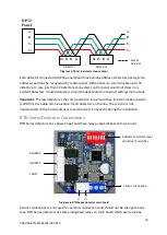
In case RS485 communciation module used on detectors to monitor through DP32 control 
panel, the V+, V- ports and A,B ports are located on different socket in both DP32 control 
panel and detector side. The connections should be done with care to do not mix power and 
RS485 ports. All detectors will be connected through one cable via hopping one detector to 
another till the last detector on the line. 

There should be one master device and up to 32 slave devices in RS485 communication. The 
master is DP32 control panel and detectors will be the slave devices: 


Diagram 4: RS485 communication 


Summary of Contents for BTN Series

Page 1: ...1 PRS UM BTN EN Rev02 02 2019 PROSENSE BTN Series Gas Detectors Installation and User Manual ...

Page 2: ...nd persons who rely on this product for their safety could suffer severe personal injury or death The warranties made by Prosense with respect to this product are voided if the product is not installed used and serviced in accordance with the instructions in this user guide Please protect yourself and other by following them Important Remark The detector has been factory tested before delivery the...

Page 3: ...on Hazards 4 Liability For Proper Function or Damage 4 Intended Use 4 Introduction 6 Detector Body 6 Sensor Head 7 Installation 7 Mounting The Detector 8 Cabling and Connections 9 BTN Series Detectors Connections 10 BTN Series Detectors Connections with RS485 Module 12 System Status 13 General Specification 15 Warranty Statement 16 ...

Page 4: ...or operator to the extent that the detector is serviced or repaired by personnel not employed or authorized by Prosense or if the sensing head is used in a manner not conforming to its intended use Prosense cannot be held responsible for damage caused by non compliance with the recommendations given above The warranty and liability provisions of the terms of sale and delivery of Prosense are likew...

Page 5: ... The measuring principle of heat of reaction needs a minimum oxygen concentration of 12 by vol otherwise the measuring values will be too low because of oxygen deficiency 3 Long term Gassing With Methane At Very Low Temperatures If the Prosense BTN series detectors are operated applying with methane at very low temperatures the measuring signal at longterm exposition may decrease after alarm activ...

Page 6: ...sirens valves or switches The detector can be configured to communicate RS485 modbus protocal with an optional module and also provides FAULT and ALARM1 relay outputs at same time Detector Body Prosense BTN series detectors comprises of the main parts as shown below Diagram 1 Exploded view The detector enclosure has four threaded entries The three cable entries either side of the upper part of the...

Page 7: ...e due to natural or forced air currents Note The placement of gas detectors should be determined following the advice of experts having specialist knowledge of gas dispersion experts having knowledge of the process plant system and equipment involved safety and engineering personnel The agreement reached on the location of detectors should be recorded Each gas has different nature depending on the...

Page 8: ...ibility for calibration work should be in air flow between possible leak or collection point and possible source of ignition Prosense do not recommend to install detectors to directly above a cooking unit directly above a sink unit close to an extractor unit outdoor without protection against the rain in places where temperature is outside the admissible operating range in corrosive environments i...

Page 9: ... 16VDC power to detector If detector has RS485 communication module additional two wire cable should be used to connect A and B to read the output signal of detector from A and B ports Connections should be made correctly with extra care to do not mix ports and not cause any damage on the detectors Detector power connection should be done with 1 5mm2 cross section cable The total distance between ...

Page 10: ...ermination resistor 120 Ohm to enable communication for all detectors on the line The resistor is not implemented on the board and user should connect it physically during the installation BTN Series Detectors Connections BTN Series detectors has a power input and three relay output sockets on main board Diagram 6 BTN Series detector main board Sensor connections are not used for external connecti...

Page 11: ...ent switches Alarm levels and related switch positions are given in table 3 Switch 6 Switch 7 Alarm1 Alarm2 OFF OFF 10 15 OFF ON 10 20 ON OFF 30 40 ON ON 40 60 Table 1 BTN Series detector alarm levels Oxygen Detectors For oxygen detectors the output values and meanings are different as oxygen is naturally available in atmosphere Alarm 1 is used to raise low level alarm and Alarm2 is used to raise ...

Page 12: ...the installation between RS485A and RS485B ports BTN series detector main board has a dip switch to assign address to the detector Each detector must have unique address to communicate to DP32 Panel Detectors having same address would not be recognised by the panel The address should be set via using first 5 switches on the dip switch Diagram 9 BTN Series detector address switches Detectors will b...

Page 13: ...inue blinking This status means that detector is ready to normal operation First time switch on Commissioning WARNING The following procedure requires the detector cover to be removed while carrying out supply voltage checks Therefore the appropriate permits to work should be sought in preparation Prior to carrying out any HOT WORK ensure local and site procedures are followed Ensure that the asso...

Page 14: ...ired accuracy can be attained To calibrate the detector use an appropriate span gas cylinder constant flow regulator and Prosense Gas Cap The flow rate used for calibration gas is 0 5 L Min Important Any optional board is installed on detector should be removed prior the calibration as some of the features masked or unavailable with them when installed Zero Calibration It is recommended to use a c...

Page 15: ...x screw terminals suitable for wire diameter 1 5mm2 to 2 5mm2 Relays 3 x 1A 30VDC 0 5A 125VAC 0 3A 80VDC Non selectable normally open and de energized Communication RS485 Modbus RTU Sensor Catalytic Table 2 BTN Series detectors electrical specifications Detector Body Specifications Material Plastic black Weight Plastic buat 230g with Sensor Header Mounting Wall mounting Entries PG11 Table 3 Detect...

Page 16: ... fault is not found with he the equipment Prosense Technology shall not be liable for any loss or damage whatsoever or howsoever occasioned which may be a direct or indirect result of the use or operation of the Contract Goods by the Buyer or any Party This warranty covers instrument and parts sold to the Buyer only by authorized distributors dealers and representatives as appointed by Prosense Te...

Reviews: