0
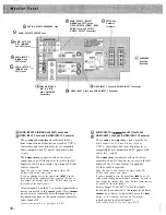
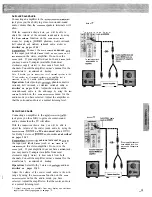
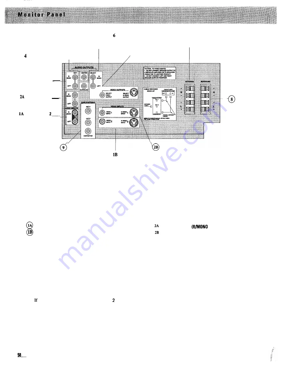
AUDIO OUPUTS (SELECT
0
7 EXTERNAL
0
R/MONO and LEFT) Jacks,
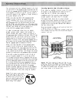
Speakers
5
AUDIO OUTPUTS SURROUND Jack
VIDEO OUTPUTS (SELECT VIDEO
Terminals
OUTPUT Jack, and SELECT
0
S-VIDEO OUTPUT Connector)
AUDIO OUTPUTS CENTER Jack
0
3 AUDIO OUTPUTS
HI-FI (R/MONO
and LEFT) Jacks
0
AUDIO INPUTS 1
(R/MONO and
LEFT) Jacks
0
AUDIO INPUTS
(R/MONO and
LEFT) Jacks
SURROUND
Speakers
Terminals
9 CABLE/ANTENNA
(ANT A, ANT B,
and CONVERTER
VIDEO INPUT 1 Jack and S-VIDEO INPUT 1 Connector
0
VIDEO INPUT 2 Jack and S-VIDEO INPUT 2 Connector
Connectors
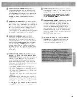
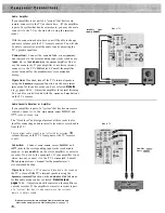
AUDIO INPUTS 2 (R/MONO and LEFT) Jacks, and
VIDEO INPUT 2 Jack, and S-VIDEO INPUT 2 Connector
These
AUDIO
and
VIDEO INPUT
2
jacks provide for
direct connection of video devices (such as VCR’ s,
camcorders, and laser disc players) or compatible
home computers and TV games with audio/video
outputs.
The
S
-
VIDEO INPUT
2
connector allows for direct
connection of an S-Video device to receive the full
benefit of the S-Video format. An optional S-Video
cable is required.
Notes: Be sure to also connect the audio cables. The
S-Video cable carries only video.
you are planning to view the signal from
INPUT
on the
small picture during picture-in-picture operation, be sure to
also connect the normal video cable. S-Video video can not
be viewed on the small picture.
Select channel 92 on the TV to see the signals from a
device connected to the
INPUT
2
jacks. Press
CHANNEL
up or down, or repeatedly press the
INPUT
button or
two number buttons on the master remote control to
select channel 92.
Connections details are on pages 66-69.
0
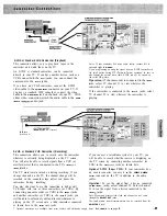
AUDIO INPUTS 1
and LEFT) Jacks, and
0
VIDEO INPUT 1 Jack, and S-VIDEO INPUT 1 Connector
These
AUDIO
and
VIDEO INPUT I
jacks provide for
direct connection of video devices (such as
VCR’ s, camcorders, and laser disc players) or
compatible home computers and TV games with
audio/video outputs.
The
S
-
VIDEO INPUT I
connector allows for direct
connection
of an S-Video device to receive the full
benefit of the S-Video format. An optional
S-Video cable is required.
Notes: Be sure to also connect the audio cables. The
S-Video cable carries only video.
If you are planning to view the signal from
INPUT 1
on the
small picture during picture-in-picture operation, be sure to
also connect the normal video cable. S-Video video can not
be viewed on the small picture.
Select channel 91 on the TV to see the signals
from a device connected to the
INPUT I
jacks. Press
CHANNEL
up or down, or repeatedly press the
INPUT
button or two number buttons on the master
remote control to select channel 9 1.
Connections details are on pages 66-69.
Summary of Contents for PS52682
Page 65: ...I I I I I I I I I I t 1 I I I I 1 II 1 I 1 ...
Page 81: ......
Page 85: ......
Page 86: ......

