ProMinent SCKa Series Operating Instructions Manual Download Page 1

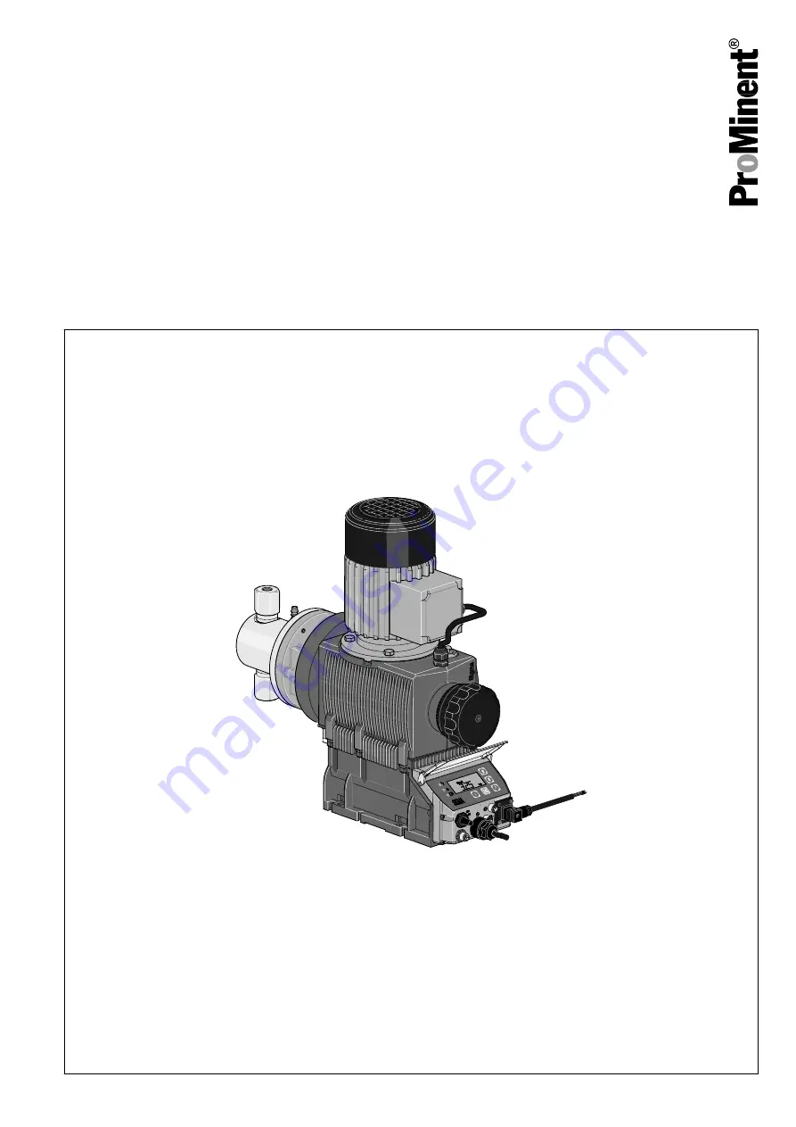
Piston Metering Pump

Sigma/ 2 Control type SCKa

Operating instructions

P_SI_0136_SW

Original operating instructions (2006/42/EC)

Part no. 984860

BA SI 060 11/13 EN

Please carefully read these operating instructions before use! · Do not discard!

The operator shall be liable for any damage caused by installation or operating errors!

Technical changes reserved.

Summary of Contents for SCKa Series

Page 1: ...0136_SW Original operating instructions 2006 42 EC Part no 984860 BA SI 060 11 13 EN Please carefully read these operating instructions before use Do not discard The operator shall be liable for any d...

Page 2: ...to the correct operation of the unit or is intended to make your work easier Safety notes Safety notes are identified by pictograms see Safety Chapter These operating instructions conform to current E...

Page 3: ...E menu 28 8 5 Operating mode settings SET menu 29 8 5 1 Manual operating mode settings 29 8 5 2 Analog operating mode settings ANALG menu 29 8 5 3 Contact operating mode settings CNTCT menu 32 8 5 4 B...

Page 4: ...7 14 6 Relay 57 14 7 Gear oil 57 14 8 Sound pressure level 57 14 9 Supplementary information for modified versions 57 15 Diagrams for adjusting the capacity 58 16 Dimensional drawings 59 17 Exploded d...

Page 5: ...th technical data Design 0 With ProMinent logo standard 1 Without ProMinent logo Electric power supply U 1 ph 100 230 V 10 50 60 Hz Cable and plug A 2 m European B 2 m Swiss C 2 m Australian D 2 m USA...

Page 6: ...Ka Sigma 2 control type Access code 0 no access code 1 with access code Dosing monitor 0 Input with pulse evaluation 1 Input with continuous evalua tion Stroke length adjustment 0 Manual Identity code...

Page 7: ...instructions n Observe the general restrictions with regard to viscosity limits chem ical resistance and density see also ProMinent Resistance List in the Product Catalogue or at www prominent com en...

Page 8: ...hnical training and experience as well as knowledge of pertinent standards and regulations Electrical technicians should be specifically trained for the working envi ronment in which they are employed...

Page 9: ...end and adjacent parts of the system Disconnect the pump from the mains power supply and ensure that it cannot be switched on again by unauthor ised persons Depressurise the system before commencing a...

Page 10: ...tructions request you to do so In the event of an electrical accident disconnect the mains cable from the mains or press the emergency cut off switch fitted on the side of the system If feed chemical...

Page 11: ...anger of material damage The device can be damaged by incorrect or improper storage or transportation The unit should only be stored or transported in a well packaged state preferably in its original...

Page 12: ...nd control elements SCKa 1 Liquid end 2 Drive motor 3 Gear bleeding plug 4 Drive unit 5 Stroke length adjustment knob 6 Control unit 75 50 Fig 3 Adjusting the stroke length n 100 10 rotations n 10 1 r...

Page 13: ...suction valve 1 into the dosing head Use the flushing collar 6 to flush the sealing surface of the piston P_SI_0144_SW 3 2 7 4 6 5 1 Fig 4 Cross section through the liquid end 1 Suction valve 2 Dosin...

Page 14: ...n also be operated in the calibrated state in all operating modes In this case the corresponding continuous displays can then indicate the metering volume or the capacity directly Calibration is maint...

Page 15: ...LED indicators and the Error identifier on the LCD screen see also the Trouble shooting chapter 5 6 LCD screen If a fault occurs the identifier Error appears and an additional error mes sage 5 7 LED d...

Page 16: ...f the pump providing it is functioning re 2 Fault Stop and Pause stop everything apart from Priming re 3 The stroke rate of Auxiliary rate always has priority over the stroke rate specified by an oper...

Page 17: ...rate CAUTION Danger from incorrectly operated or inadequately maintained pumps Danger can arise from a poorly accessible pump due to incorrect operation and poor maintenance Ensure that the pump is ac...

Page 18: ...y too low Vibrations can disrupt the liquid end valves Secure the metering pump so that no vibrations can occur Take the dimensions m for the fastening holes from the appropriate dimensional drawings...

Page 19: ...pressed air through the suction connector Then flush the liquid end with a suitable medium through the suction connector WARNING The following measures are an advantage when working with highly aggres...

Page 20: ...emical Feed chemicals can leak through a stopped metering pump if there is back pressure Use an injection valve or a vacuum breaker CAUTION Uncontrolled flow of feed chemical Feed chemical can leak th...

Page 21: ...iquid is drained off via the flushing collar and a hose nozzle without other parts of the liquid end coming into contact with the medium 1 Connect a hose to the lower hose nozzle 2 Route the hose into...

Page 22: ...l pacing cable or the level monitoring cable is shortened below 1 20 m the pump does not detect that it is connected Consequently a warning message for example can be suppressed Do not shorten this ca...

Page 23: ...tact CSA cable 1 white NO normally open white 2 green NC normally closed red 4 brown C common black As a NC fault indicating relay the relay closes immedi ately after the power is switched on and open...

Page 24: ...rown C common Pacing relay As a NC fault indicating relay the relay closes immedi ately after the power is switched on and opens in the event of a fault As a N O fault indicating relay the relay close...

Page 25: ...ng relay 2 brown C common Pacing relay 7 2 2 Pump power supply 1 Install an emergency cut off switch or include the pump in the emer gency cut off management of the system 2 Install the pump cable Key...

Page 26: ...hanges to the next menu option or into a continuous display Press and hold the P key for 3 seconds Entry is cancelled and you jump back to a continuous display B0083 Fig 16 a Toggle between changing o...

Page 27: ...ontin uous display The display does not contain the P key symbol Each press of the i key toggles the continuous display output to the screen to another continuous display The number of continuous disp...

Page 28: ...r and PROFIBUS Note the diagram 8 4 Selecting the operating mode MODE menu In the MODE menu dependent on the identity code some operating modes may not be present n Manual for manual operation identit...

Page 29: ...connected see also the chapter Programmable function settings SET menu As to whether or not a further setting menu is available depends on the selected operating mode 8 5 1 Manual operating mode sett...

Page 30: ...nal For current signals less than 3 8 mA a fault message appears and the pump stops e g if a cable has broken n Curve Under the Curve processing type you can freely program the pump behaviour There ar...

Page 31: ...reen Below I1 the pump works at a rate of F1 above I2 it stops Between I1 and I2 the stroke rate varies between F1 and F2 in proportion to the signal current I mA I 1 I 2 F2 F1 0 20 a b P1 P2 Fmax B00...

Page 32: ...The purpose of this operating mode is to convert the incoming pulses with a reduction fractions or small step up into strokes CAUTION If you change into another operating mode the factor is reset to...

Page 33: ...ctor Pulse and strokes with a factor 1 1 stroke is completed after 1 pulse with a factor 0 5 1 stroke is completed after 2 pulses with a factor 0 1 1 stroke is completed after 10 pulses with a factor...

Page 34: ...erating adjustment overview in the appendix Batch operating mode is intended for large metering quantities The metering can be triggered either by pressing the P key or by a pulse received via the Ext...

Page 35: ...is possible If the feed chemical is dangerous take appropriate safety precautions when carrying out the following han dling instructions Observe the feed chemical safety data sheet 1 Lead the suction...

Page 36: ...frequency is being used then the identifier Aux appears in the LCD screen This auxiliary frequency has priority over the stroke rate which is specified by the currently selected operating mode 8 6 3 F...

Page 37: ...isplays in Operating adjustment over view in the appendix In the next menu option enter the number you want to use as the code n Select NONE to clear a set security lock 8 8 Deleting the total number...

Page 38: ...point of view be accurately reproduced is 10 100 At low stroke rates the pump control switches to stop and go operation This occurs with stroke rates which are less than 1 3 of the maximum stroke rate...

Page 39: ...The factor is the number of strokes which are triggered upon an external pulse or pressing of key P only in Batch operating mode In operating mode Batch You can change the factor from the Remaining st...

Page 40: ...de Acknowledge errors Check adjustable values 2 2 1 1 9 2 Remote operation There is an option to control the pump remotely via a signal cable PRO FIBUS or CAN bus see chapter Settings selecting the op...

Page 41: ...rs Disconnect the pump from the mains power supply and ensure that it cannot be switched on again by unauthor ised persons WARNING Risk of injury from the fan impeller The fan impeller beneath motor s...

Page 42: ...seated Check the correct seating and state of the metering lines at both discharge and suction ends Check the leak tightness of the entire liquid end Check whether the leakage level is OK 10 120 drops...

Page 43: ...1 2 Place an oil trough under the oil drain plug 2 3 Unscrew the oil drain plug 2 from the power end housing 4 Allow the gear oil to run out of the power end 5 Screw in the oil drain plug 2 with a ne...

Page 44: ...e switched on again by unauthor ised persons WARNING Risk of injury from the fan impeller The fan impeller beneath motor s fan cowling can cause severe injuries while it is turning The pump must only...

Page 45: ...of the valve seat 3 n one ball 5 into the valve body 1 n one seal 2 and the second valve seat 3 correct n one seal 2 and the second valve bushing 4 n If fitted the second spring into the spring guide...

Page 46: ...against the feed chemical protective clothing safety glasses After dismantling immediately place parts that have been wetting with the medium in a trough with a suitable medium for flushing in danger...

Page 47: ...rews 25 of the dosing head flange 3 and remove the dosing head flange 3 Loosen the screws 27 of the guide ring 5 and remove it 4 Remove the flushing collar 4 the V sleeve packing 20 the washer 6 and s...

Page 48: ...tighten the guide ring 5 with a new guide band 24 on the dosing head 8 Tighten the screws 27 Tightening torque 5 Nm 9 Place the dosing head flange 3 on the liquid end and tighten Tightening torque 7 N...

Page 49: ...4 Attach the upper protective cover to the turret 5 If fitted Connect the flushing tubes to the hose nozzles Repairs 49...

Page 50: ...rsons Depressurise the system before commencing any work on hydraulic parts 12 1 Faults without a fault alert Fault description Cause Remedy Personnel Green LED display operating dis play does not lig...

Page 51: ...an was set in the FLOW menu Press the P key Investigate and clear the cause The red LED indicator illuminates on the dis play the identifiers Error and MOTOR flash Due to too high back pressure the mo...

Page 52: ...liquid level low 1st stage Fill storage tank Green LED indicator illuminates and the identifier Calib flashes The pump is calibrated and the stroke length varies by more than 10 scale divisions from t...

Page 53: ...y clean the liquid end and the housing of chemicals and dirt Adhere to the safety data sheet for the feed chemical WARNING Warning of dangerous or unknown feed chemical Should a dangerous or unknown f...

Page 54: ...erve the safety data sheet Flush the dosing head thoroughly when using haz ardous feed chemicals 5 Possible additional work see chapter Storage Transport and Unpacking Personnel n Technical personnel...

Page 55: ...030 7 1 1 80 84 4 70 1 4 10011 100 1450 13 1 3 40 154 4 50 1 4 05016 50 725 16 7 4 4 200 4 25 1 4 07012 70 1015 14 8 3 90 84 4 35 1 4 04522 45 652 26 7 7 00 154 4 22 5 1 4 02534 25 362 34 1 9 00 200 4...

Page 56: ...nd Suction pressure connector Seals ball seat Balls Ball seat Piston Stainless steel 1 4571 1 4404 Stainless steel 1 4571 1 4404 PTFE or PTFE with graphite Oxide ceramic Stainless steel 1 4571 1 4404...

Page 57: ...ion Version M modified Technical data of pumps in the modified version can deviate from those of the standard pumps They can be queried by stating the details of the serial number During operation wit...

Page 58: ...0 100 120 05016 10011 14006 10006 23004 32002 0 5 10 15 20 25 0 10 20 30 40 50 60 70 80 90 80 70 60 50 40 30 20 0 10 01264 02541 02534 04522 04022 07012 0 5 10 15 20 25 0 50 100 150 200 250 300 350 05...

Page 59: ...37 Dimensional drawing Sigma SCKa dimensions in mm Type Liquid end A B C 32002 23004 10006 FK 08 267 164 Rp 1 4 DN8 14006 10011 05016 FK 12 5 267 164 Rp 1 4 DN8 07012 04522 02534 FK 25 267 164 Rp 1 4...

Page 60: ...17 Exploded drawing Sigma piston metering pump 4x 4x 2x 2x P_SI_0137_SW Fig 38 The items listed are included in the spare parts kit Liquid end Exploded drawing Sigma piston metering pump 60...

Page 61: ...d Exploded drawings ProMinent product catalogue www prominent com en downloads Spare parts kit Types 32002 23004 10006 Types 14006 10011 05016 Types 07012 04522 02534 Types 04022 02541 01264 FK 08 100...

Page 62: ...nt of a modification to the product not agreed with us Extract from the EC Declaration of Conformity Designation of the product Metering pump Sigma product range Product type SBKa and SCKa Serial numb...

Page 63: ...Continuous display Stop start pump Change directly changeable variables Lock CODE 1 Lock CODE 2 Prime Start batch only in Batch operating mode Acknowledge errors Check adjustable values P_SI_0040_SW...

Page 64: ...Set P Set Set Set Calib Set Calib Set Set Set P_SI_0039_SW Operating adjustment overview 64...

Page 65: ...roke rate Capacity Total number of strokes Total litres metering quantity External display Signal current Remaining strokes Batch size Remaining litres Factor Stroke length B0100 B0101 B0102 B0103 val...

Page 66: ...umber of strokes or total litres 37 Designation of the product 62 Diagrams 58 Dimensional drawings 59 Discharge valve 13 Disposal 54 Dosing head 13 Dosing monitor 36 Draining the liquid end 54 Drive m...

Page 67: ...s 62 Repairs 44 Reproducibility 55 S Safety chapter 7 Scope of supply 11 Serial number 62 SET menu 29 34 Set up 26 Shipping weight 56 Sound pressure level 10 57 Spare parts 57 60 Spare parts kits 61 S...

Page 68: ...986265 1 en_GB 2011 ProMinent Dosiertechnik GmbH Im Schuhmachergewann 5 11 69123 Heidelberg Germany Telephone 49 6221 842 0 Fax 49 6221 842 612 email info prominent com Internet www prominent com...

Reviews: