ProMinent S3Ba 120145 PVT Operating Instructions Manual Download Page 1

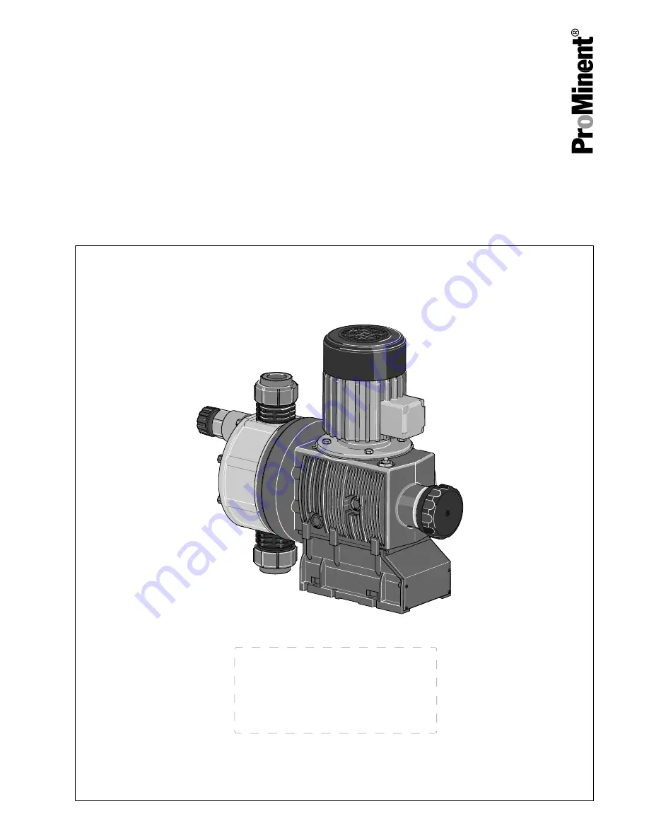
Diaphragm motor-driven metering pump

Sigma/ 3 Basic type S3Ba

Operating instructions

P_SI_0075_SW

EN

Original operating instructions (2006/42/EC)

Part no. 985905

BA SI 089 01/19 EN

Please carefully read these operating instructions before use. · Do not discard.

The operator shall be liable for any damage caused by installation or operating errors.

The latest version of the operating instructions are available on our homepage.

Summary of Contents for S3Ba 120145 PVT

Page 1: ...perating instructions 2006 42 EC Part no 985905 BA SI 089 01 19 EN Please carefully read these operating instructions before use Do not discard The operator shall be liable for any damage caused by in...

Page 2: ...to the cor rect operation of the unit or is intended to make your work easier Safety notes Safety notes are identified by pictograms see Safety Chapter These operating instructions conform to current...

Page 3: ...ragm 58 13 Troubleshooting 62 14 Decommissioning 65 15 Technical data 68 15 1 Performance data 68 15 2 Shipping weight 69 15 3 Wetted materials 70 15 4 Ambient conditions 70 15 4 1 Ambient temperature...

Page 4: ...22 Declaration of Conformity for Machinery 94 23 Declaration of Incorporation for Machinery 95 24 Declaration of Conformity for ATEX Machinery 96 25 Declaration of Conformity for ATEX Machinery 97 26...

Page 5: ...th DN 32 4 with relief valve FPM seal no valve springs 5 with relief valve FPM seal with valve springs standard with DN 32 6 with relief valve EPDM seal no valve spring 7 with relief valve EPM seal wi...

Page 6: ...ength adjustment 0 manual standard 1 2 Connection data refer to nameplate on servomotor 3 6 Connection data refer to nameplate on stroke control motor ATEX specification refer to the nameplate on the...

Page 7: ...e temperature 135 C Equipment protection level EPL Gb high EPL in normal operation and in the event of expected errors corre sponds to category 2G Gc normal EPL in normal operation corre sponds to cat...

Page 8: ...isted in the table with equipment approved for explosion group IIC and temperature class T4 Equipment approved for explosion group IIB can also be used for explosion group IIA not for explosion group...

Page 9: ...voltage Warning danger zone n Only use the pump to meter liquid feed chemicals n Only pumps with the identity code option Multi layer safety diaphragm with visual rupture display and Multi layer safet...

Page 10: ...e requirement Explanation of the table Trained qualified personnel A trained qualified employee is deemed to be a person who is able to assess the tasks assigned to him and recognise possible hazards...

Page 11: ...strike The customer must put in place suitable protective meas ures outdoors Static electricity The customer must earth the earthing points and maintain the potential equalisation cables of the indivi...

Page 12: ...e air inlet on the fan hood and any obstacles Avoid deposits of dust more then 5 mm deep Connect the earth wire Max installation height 1 000 m a s l Ignition hazard with bought in actuator or control...

Page 13: ...ts of the system Disconnect the pump from the mains power supply and ensure that it cannot be switched on again by unauthorised persons Depressurise the system before commencing any work on hydraulic...

Page 14: ...create the legal framework for the safe operation of the system or system component such as for example the preparation of operating instructions operator s duties All isolating protective equipment m...

Page 15: ...radiation or ultrasound or lightning without putting in place measures in line with EN 80079 38 n Do not allow the ATEX design to meter media which tends to produce exothermic reactions or self ignit...

Page 16: ...chnician with an additional explosion protection qualification can work on electrical systems and independently recognise and avoid possible dan gers based on his technical training and experience The...

Page 17: ...ures in accordance with EN 1127 1 if need be Adiabatic compression and shock waves Feed chemical with electrical conductivity of 50 pS m which could form a combustible mixture Do not allow the unit to...

Page 18: ...in sufficient clearance between the air intake opening and the walls The distance should be greater than 1 4 of the diameter of the air intake opening The fan must not suck in the exhaust air from oth...

Page 19: ...cleanly and per manently to an electrically clean earthing point e g with an earthing bar on your system Electrically connect the electrical units fitted with a potential equalisation cable to each ot...

Page 20: ...the enclosed operating instructions for the Ex motor Only use a moist cloth when cleaning plastic parts Prevent serious deposits of dust on the motor Consider potential equalisation before you approa...

Page 21: ...range of 2 Hz limited torque to 100 Hz The pulse frequency of the frequency converter is 4 kHz Check the pump installation for n Leaks n Abnormal noises or squeaks n Abnormal temperatures n Abnormal...

Page 22: ...er ating pressure 90 C Minimum temperature 10 C Data Value Unit Maximum installation height 1000 m above standard zero We urgently advise you to contact a specialist for ATEX motors with higher intend...

Page 23: ...laration of Conformity fit your own company nameplate 4 With ATEX pumps additionally perform an ignition hazard assess ment 5 Complete the pump documentation operating instructions Refer to the end of...

Page 24: ...25 Temperature class T3 for Temperature class T3 gas Refer to the material safety data sheet for the gas or for example Tab 2 Example of the division of gases into explosion groups and temperature cl...

Page 25: ...classes T4 T3 T2 T1 IIC Ethyne Hydrogen IIB Ethyl ether Ethene Mains gas coal gas IIA Acetaldehyde Benzine Diesel fuel Aircraft fuel Heating oils n hexane Ethanol n butane n butyl alcohol Acetone Ammo...

Page 26: ...fted into its final position CAUTION Danger of material damage The device can be damaged by incorrect or improper storage or transportation The unit should only be stored or transported in a well pack...

Page 27: ...pment and control elements S3Ba 1 Drive motor 2 Drive unit 3 Stroke length adjustment knob 4 Liquid end with relief valve 5 Diaphragm rupture sensor 1 2 P_SI_0088_SW Fig 4 Sigma control elements 1 Rel...

Page 28: ...length n 100 4 rotations n 25 1 rotation n 0 5 1 scale mark on stroke adjustment dial PG11 PG9 1 2 3 A B P_SI_0036 Fig 6 Front cover for version with pacing relay A Pacing relay cable B Supply voltag...

Page 29: ...One cycle is thus completed 4 2 1 5 3 13 Fig 7 Cross section through the liquid end 1 Suction valve 2 Diaphragm 3 Discharge valve 4 Dosing head 5 Backplate 13 Safety diaphragm 5 3 Integral relief valv...

Page 30: ...in the event of a diaphragm rup ture the lowered red cylinder 6 springs forward beneath the transparent cover 7 so that it then becomes clearly visible see Fig 9 With the electrical diaphragm rupture...

Page 31: ...ight see Fig 10 3 Secure set screws and threaded connections to prevent them from loosening WARNING EX is relevant in areas at risk from explosion 4 As you have converted an incomplete machine into a...

Page 32: ...y overheat In an area at risk from explosion it could trigger an explosion Maintain sufficient clearance between the air intake opening and the walls The distance should be greater than 1 4 of the dia...

Page 33: ...discharge valve is upright Capacity too low Vibrations can disturb the liquid end valves Secure the metering pump so that no vibrations can occur Take the dimensions m for the fastening holes from the...

Page 34: ...used for metering flam mable media but fundamentally only those designed with an ATEX diaphragm rupture sensor and a discharge side flow control which both stop the pump as soon as a diaphragm ruptur...

Page 35: ...missible pressure of the system or the metering pump This could lead to lines bursting resulting in dan gerous consequences with aggressive or toxic feed chemicals Install a relief valve that limits t...

Page 36: ...l seals Do not route feed chemical that escapes from the integral bleed valve or the integral relief valve back into the process CAUTION Danger due to incorrect use of the integral relief valve The in...

Page 37: ...fed into the suction line the bleed function is blocked Therefore lead the overflow line back into the storage tank When operating the integral relief valve close to the opening pressure a minimal ove...

Page 38: ...emicals Hazardous feed chem ical can leak out when using conventional bleeding pro cedures with metering pumps Install a bleed line with return line into the storage tank Shorten the return line so th...

Page 39: ...for the individual electrical components WARNING Danger of fire with flammable feed chemicals The ATEX diaphragm rupture sensor and a dis charge side flow control must both stop the pump as soon as a...

Page 40: ...fre quency converter Only open the drain screw 3 minutes after the mains voltage has been switched off WARNING Never change the Motor voltage and Cycle frequency parameters with motor designs with int...

Page 41: ...ppropriate motor protection devices e g motor protection switch with thermal overcurrent trip to protect the motor from overloading Fuses do not provide motor protection CAUTION Operation of the syste...

Page 42: ...s special motors special motor flanges external fan temperature monitoring For further information on the motor with identity code specification S refer to our website www prominent com Motor data she...

Page 43: ...le can be connected as required b Namur sensor inherently safe Make sure that the monitoring feed equipment installed by the customer is capable of evaluating the current variations of the Namur senso...

Page 44: ...relay becomes too high it can be destroyed by heating Fit a circuit breaker Pacing relay terminal output data Data Value Unit Maximum voltage 24 VDC Maximum current 100 mA Closing duration approx 100...

Page 45: ...necessary potential equalisation lines Electrically connect an additional potential equalisation cable from the potential equalisation cables from this system cleanly and permanently to an electrical...

Page 46: ...er of elec tric shock The danger of electric shock remains for 3 minutes after the mains voltage has been switched off on conducting parts of the motor with an integrated frequency converter and on th...

Page 47: ...material damage Observe the details in the chapter Technical data pressure viscosity resistance etc Check that the installation complies with the regulations CAUTION Danger resulting from unnoticed d...

Page 48: ...er the drive motor is rotating correctly check this against the arrow on the motor housing or the dia gram in the chapter entitled Electrical Installation WARNING Risk of injury from the fan impeller...

Page 49: ...rted When operating the integral relief valve close to the opening pressure a minimal overflow into the overflow line can occur Only adjust the stroke length when the pump is running This is easier an...

Page 50: ...injury and material damage may occur During use all units protective equipment additional devices must be fitted operational and tightly closed WARNING Sparking caused by dry running If the bearings i...

Page 51: ...ld be at a different electrical potential such as pipes or tools Only with stroke control motor Wait 3 minutes after switching off before opening the housing Replace wear parts such as bearings when t...

Page 52: ...arning of hazardous feed chemical Should a dangerous feed chemical be used it may escape from the hydraulic components when working on the pump material failure or incorrect handling of the pump Take...

Page 53: ...hat the diaphragm rupture sensor is firmly seated n Check whether the diaphragm rupture sensor stops the pump or generates an alarm after it has been triggered n Check that the flow is correct Allow t...

Page 54: ...glasses Draining gear oil 1 3 2 P_SI_0143_SW Fig 21 1 Remove the vent screw 1 2 Place an oil trough under the oil drainage plug 2 3 Unscrew the oil drainage plug 2 from the power end housing 4 Allow t...

Page 55: ...WARNING Only in areas at risk from explosion Check after 1 day whether the oil drainage plug 2 is still tight Maintenance 55...

Page 56: ...ning of feed chemical spraying around Feed chemical can spray out of the hydraulic compo nents if they are manipulated or opened due to pressure in the liquid end and adjacent parts of the system Disc...

Page 57: ...cal personnel CAUTION Warning of personal injury and material damage Feed chemical may escape from the liquid end for example if ball valves not repaired correctly Only use new components which fit yo...

Page 58: ...he stop at 0 stroke length The drive axle is now difficult to turn 3 Switch off the pump 4 Unscrew the hydraulic connectors on the discharge and suction side 5 Unscrew the diaphragm rupture sensor fro...

Page 59: ...caping feed chemical The liquid end may leak should it not be possible to check the tightening torque of the screws Check the tightening torque of the screws after 24 hours of operation With PP PC and...

Page 60: ...s the red cylinder into the diaphragm rupture sensor again and repeat the test 5 If it does not trigger both times replace the membrane rupture sensor 6 After a successful test screw the transparent c...

Page 61: ...4 2 1 5 3 13 P_SI_0038 Fig 25 Cross section through the liquid end 1 Suction valve 2 Diaphragm 3 Discharge valve 4 Dosing head 5 Backplate 13 Safety diaphragm Carrying out repairs 61...

Page 62: ...be ignited by oxygen The pump may not work if there is a mixture of feed chemical with oxygen in the liquid end A specialist may need to take appropriate actions using inert gas WARNING Danger of an...

Page 63: ...cing any work on hydraulic parts Fault description Cause Remedy Personnel Pump does not prime in spite of full stroke motion and bleeding The valves are dirty or worn Repair the valves see chapter ent...

Page 64: ...plosion under no circumstances must the second diaphragm also rupture If the pump diaphragm rupture sensor triggers stop the pump immediately and only operate once a new multi layer safety diaphragm h...

Page 65: ...al residue There is normally chemical residue in the liquid end and on the housing after operation This chemical residue could be hazardous to people It is mandatory that the safety information in the...

Page 66: ...stem is decommissioned for a temporary period 1 Disconnect the pump from the mains 2 Depressurise and bleed the hydraulic system around the pump 3 Drain the liquid end by turning the pump upside down...

Page 67: ...gear oil from the pump Note the local guidelines currently applicable in your country In accordance with the European Directive 2012 19 EU on waste electrical and electronic equipment this device fea...

Page 68: ...7 103 5 2 1 1 2 DN25 120270 PVT 10 292 33 8 144 5 2 1 1 2 DN25 120270 SST 12 292 33 8 144 5 2 1 1 2 DN25 120330 PVT 10 365 33 8 180 5 2 1 1 2 DN25 120330 SST 12 365 33 8 180 5 2 1 1 2 DN25 070410 PVT...

Page 69: ...N32 070410 SST 7 102 492 130 86 4 1 2 DN32 070580 PVT 7 102 696 183 124 4 1 2 DN32 070580 SST 7 102 696 183 124 4 1 2 DN32 040830 PVT 4 58 1000 264 173 3 1 2 DN32 040830 SST 4 58 1000 264 173 3 1 2 DN...

Page 70: ...VC PTFE Ceramic hast C CTFE PTFE PVDF FPM or EPDM PVT PVDF PTFE Ceramic hast C CTFE PTFE PVDF FPM or EPDM TTT PTFE 25 carbon PVDF Ceramic 1 4404 Hast C CTFE PTFE PVDF FPM or EPDM SST Stainless steel 1...

Page 71: ...ure long term at max oper ating pressure 90 C Max temperature for 15 min at max 2 bar 120 C Minimum temperature 10 C not in areas at risk from explosion 15 4 3 Air humidity Data Value Unit Maximum air...

Page 72: ...2G Ex h IIC Gb T4 X 220 240 V 380 420 V 50 Hz 0 37 kW with PTC speed control range 1 5 P1 3 phase II 2G Ex h IIC Gb T3 X 250 280 V 440 480 V 60 Hz 0 37 kW P2 3 phase II 2G Ex h IIC Gb T4 X 250 280 V 4...

Page 73: ...ve low voltage e g in accordance with EN 60335 1 SELV The cable can be connected as required Install the sensor in accordance with the chapter Instal lation electrical Refer to its documentation Senso...

Page 74: ...DC in accordance with Namur or DIN 60947 5 6 potential free design Data Value Unit Nominal voltage 8 VDC Power consumption active surface uncovered 3 mA Power consumption active surface cov ered 1 mA...

Page 75: ...om those of the standard pumps They can be queried by stating the details of the serial number During operation with an automatic stroke length adjustment control together with a variable speed motor...

Page 76: ...4 2 500 0 1100 1000 900 800 700 600 300 400 100 200 041030 040830 070580 070410 0 20 40 60 10 30 50 80 70 90 100 300 0 500 400 100 200 120270 120190 120145 0 1 6 10 12 9 7 5 0 300 500 400 100 11 8 4 3...

Page 77: ...or A B C D E F G I I K Sigma 120145 120190 120270 120330 PVT TTT DN25 296 237 G 1 1 2 male 122 358 74 156 140 166 64 Sigma 120145 120190 120270 120330 SST DN10 295 236 G 1 1 2 male 122 349 88 156 147...

Page 78: ...4 male DN10 SSA SSE 16 G 3 4 DN20 PVA PVE 25 35 5 G 1 1 4 male DN20 SSA SSE 25 G 1 Tube nozzle and union nut Insert and union nut P_SI_0054_SW_2 61_01 101_00_12 73 Fig 28 Dimensional drawing of Sigma...

Page 79: ...g 29 Dimensional drawing of Sigma 3 S3Ba with physiologically safe liquid end dimensions in mm Drawing is not strictly binding Dimensional drawing of Sigma 3 S3Ba with physiologically safe liquid end...

Page 80: ...0330 PVT TTT DN25 286 237 G1 1 2 male 62 331 74 156 130 156 64 120145 120190 120270 120330 SST DN25 285 236 G1 1 2 male 62 322 88 156 137 60 070410 070580 040830 041030 PVT PPT PCT TTT DN32 316 298 G2...

Page 81: ...connectors on relief valve M M M DN10 PVA PVE 16 21 4 G 3 4 male DN10 SSA SSE 16 G 3 4 male DN20 PVA PVE 25 35 5 G1 1 4 male DN20 SSA SSE 25 G1 Tube nozzle and union nut Insert and union nut Dimensio...

Page 82: ...0_SW 6 A B Fig 31 Potential equalisation drawings for Sigma S3Ba A Pump without frame B Pump with frame 1 Potential equalisation of motor 2 Potential equalisation of motor flange 3 Potential equalisat...

Page 83: ...otential equalisation of stroke sensor Potential equalisation of frame Positions 1 2 5 and 6 must be connected to a protective earth cable Positions 3 and 4 must be connected to a protective earth cab...

Page 84: ...1400 1700 U min Bauform Bemessungsdrehzahl mounting rated speed rpm Bemessungsleistung 0 37 kW 50Hz W rmeklasse F rated output 0 42 kW 60Hz temperature class Bemessungsspannung Anzugsstrom 4 In fach r...

Page 85: ...45 120190 120270 120330 1 Spring 2 Ball 3 Ball seat 4 Diaphragm rupture sensor optical 1033323 5 Valve 740615 6 Multi layer diaphragm 1029604 The items listed are included in the spare parts kit Speci...

Page 86: ...ype 070410 070580 040830 041030 1 Spring 2 Ball 3 Ball seat 4 Diaphragm rupture sensor optical 1033323 5 Valve 1020031 6 Multi layer diaphragm 1029603 The items listed are included in the spare parts...

Page 87: ...40830 041030 10 Relief valve complete 10 bar PVA 1005626 10 Relief valve complete 7 bar PVA 1004801 10 Relief valve complete 4 bar PVA 1004778 The items listed are included in the spare parts kit Spri...

Page 88: ...Spring 2 Ball 3 Ball seat 4 Diaphragm rupture sensor optical 1033323 5 Valve 803706 6 Multi layer diaphragm 1029604 The items listed are included in the spare parts kit Special accessories not include...

Page 89: ...120330 1 Spring 2 Ball 3 Ball seat 4 Diaphragm rupture sensor optical 1033323 5 Valve 803708 6 Multi layer diaphragm 1029604 The items listed are included in the spare parts kit Special accessories n...

Page 90: ...on Type 070410 070580 040830 041030 1 Spring 2 Ball 3 Ball seat 4 Diaphragm rupture sensor optical 1033323 5 Valve 1002811 6 Multi layer diaphragm 1029603 The items listed are included in the spare pa...

Page 91: ...0830 041030 10 Relief valve complete 12 bar SSA 1005625 10 Relief valve complete 7 bar SSA 1005038 10 Relief valve complete 4 bar SSA 1005042 The items listed are included in the spare parts kit Sprin...

Page 92: ...sion Seals Order no ETS relief valve 4 bar PVT SST FKM A EPDM 1031204 ETS relief valve 7 bar PVT SST FKM A EPDM 1031205 ETS relief valve 10 bar PVT FKM A EPDM 1031201 ETS relief valve 12 bar SST FKM A...

Page 93: ...d end Suction pressure connector Seals ball seat Balls Integrated bleed valve or relief valve PVT PVDF PVDF PTFE PVDF Glass PVDF EPDM SST Stainless steel 1 4404 Stainless steel 1 4581 PTFE PVDF Stainl...

Page 94: ...rom the Declaration of Conformity Designation of the product Metering pump Sigma product range Product type S3Ba _ _ _ _ _ _ _ _ _ _ _ _ _ _ _ 0 _ _ with characteristics M or N or R or S or T or V or...

Page 95: ...rom the Declaration of Conformity Designation of the product Metering pump without motor Sigma product range Product type S3Ba _ _ _ _ _ _ _ _ _ _ _ _ _ _ 0_ _ with characteristics 1 or 2 or 3 Serial...

Page 96: ...14 34 EC Machinery Directive 2006 42 EC Compliance with the protection targets of the Low Voltage Directive 2014 35 EU according to Appendix I No 1 5 1 of the Machinery Directive EMC Directive 2014 30...

Page 97: ...ee nameplate on the unit Relevant directives ATEX Directive 2014 34 EU Machinery Directive 2006 42 EC Compliance with the protection targets of the Low Voltage Directive 2014 35 EU according to Append...

Page 98: ...cal data 72 Emergency 14 EU Declaration of Conformity 96 EU Declaration of Incorporation 97 External fan 41 72 F Form 75 G Gear oil 75 Guard plate 72 I Identification of safety notes 9 Identity code 5...

Page 99: ...rage 26 Storage and transport temperature 70 Stroke actuator 73 Stroke control drive 73 Stroke length 49 Stroke length adjustment control 75 Stroke length adjustment knob 27 Stroke sensor 43 74 Suctio...

Page 100: ...985905 2 en_GB 2011 ProMinent GmbH Im Schuhmachergewann 5 11 69123 Heidelberg Germany Telephone 49 6221 842 0 Fax 49 6221 842 419 Email info prominent com Internet www prominent com...

Reviews: