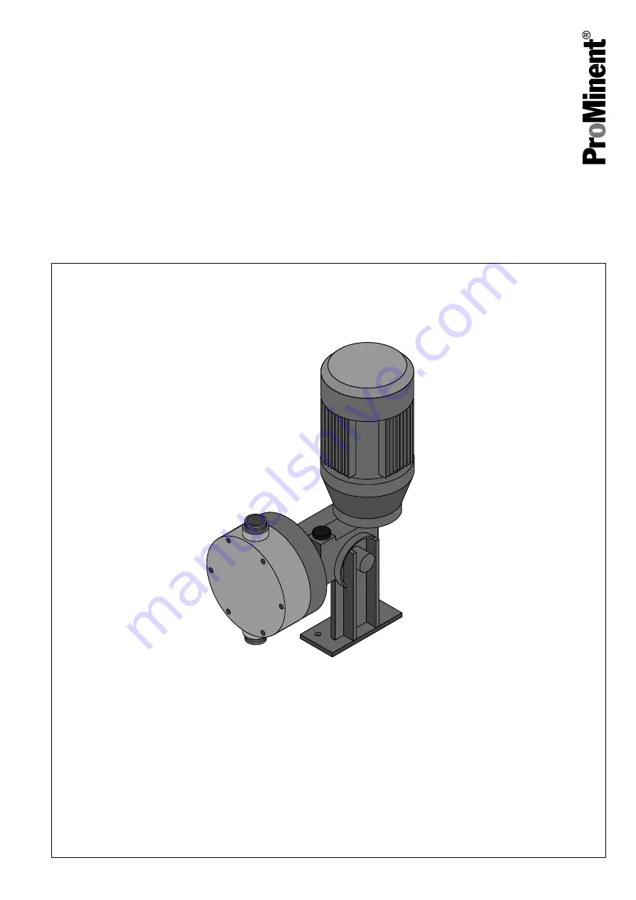
ProMinent Plasma PSMa Operating Manual Download Page 1

Plasma PSMa

Motorised Diaphragm Metering Pump

Operating Manual

P_PL_0001_SW

Two sets of operating instructions are required for the safe, correct and proper operation of the metering pumps: The

product-specific operating instructions and the "General Operating Instructions ProMinent

® 

 Motor-Driven Metering Pumps

and Hydraulic Accessories".
Both sets of operating instructions are only valid when read together.

Translation of Original operating instructions (2006/42/EC)

Vers. 10/2009

Please carefully read these operating instructions before use! · Do not discard!

The operator shall be liable for any damage caused by installation or operating errors!

Technical changes reserved.

Summary of Contents for Plasma PSMa

Page 1: ...nd the General Operating Instructions ProMinent Motor Driven Metering Pumps and Hydraulic Accessories Both sets of operating instructions are only valid when read together Translation of Original oper...

Page 2: ...Heidelberg ProMinent Fluid Controls India Pvt Ltd 2 2 M E S Road Yeshwanthpur Bangalore 560 022 India Telephone 080 2357 8872 73 74 Fax 080 2357 3743 2347 7984 email prominent hpfcindia com Internet w...

Page 3: ...ired for the safe correct and proper operation of the metering pumps The product specific operating instructions and the General Operating Instructions ProM inent Motor Driven Metering Pumps and Hydra...

Page 4: ...Valves 22 11 2 Replacing the Diaphragm 24 12 Troubleshooting 26 13 Decommissioning 27 14 Technical Data 29 14 1 Performance Data 29 14 2 Degree of Protection and Safety Requirements 29 14 3 Ambient Co...

Page 5: ...material TT PTFE with PTFE sealing material SS Stainless steel with PTFE sealing material Dosing head design 0 Standard Hydraulic connection 0 Standard connection cap nut with hose connection 1 Cap nu...

Page 6: ...are compact energy saving provide excellent precision and reflect the high standards of quality of ProMinent motorised metering pumps ProMinent Plasma PSMa motorised metering pumps are available up t...

Page 7: ...cal voltage n The pump may only be used to dose liquid feed chemicals n The pump may only be used after it has been correctly installed and commissioned in accordance with the technical data and speci...

Page 8: ...cal spraying around An unsuitable feed chemical can damage the parts of the pump contacted by the chemical Take into account the resistance of the material contacted by the chemical when selecting the...

Page 9: ...ise and avoid possible hazards independently based on his her technical training and experience as well as knowledge of pertinent standards and regulations Electricians should be specifically trained...

Page 10: ...ndix or at www prominent com CAUTION Danger of environmental and material damage The unit can be damaged or oil may escape due to incorrect or improper storage or transportation The unit should only b...

Page 11: ...in a dry sealed place in the following ambient condi tions Specification Value Unit Minimum storage and transport temperature 10 C Maximum storage and transport temperature 50 C Maximum air humidity...

Page 12: ...3 4 P_PL_0002_SW 2 5 6 Fig 2 Complete overview 1 Drive motor 2 Bleed plug Locking plug 3 Liquid end 4 Oil drain screw 5 Drive unit 6 Stroke length adjustment knob not shown Oil level indicator on rear...

Page 13: ...can be adjusted by the stroke adjustment knob 6 and the shaft 7 The different stroke lengths are in effect caused by the limitation of the return stroke cf Illustration of the stroke movement on page...

Page 14: ...of the dosing head through the discharge valve 1 As soon as the diaphragm 3 is moved in a counter direction the discharge valve 1 closes due to the negative pressure in the dosing head and fresh feed...

Page 15: ...preferably in its original pack aging Only transport the unit with the locking screw not the bleed plug fitted to the oil filling opening The packaged unit should also only be stored or transported in...

Page 16: ...tor Driven Metering Pumps and Hydraulic Accessories Personnel n Technical personnel 8 2 Electrical Installation WARNING Risk of electric shock The electrical installation of the unit may only be under...

Page 17: ...rotation of motor Key motor data can be found on the unit specification label The terminal wiring diagram is located in the terminal box The motor can only be wired in star Y configura tion Personnel...

Page 18: ...When the pump is idle check whether the oil level in the pump is in the middle of the oil level indicator This will rule out the pump losing oil and suffering damage When commissioning the unit check...

Page 19: ...ess than 30 for precise dosing Eliminating priming problems only with TTT and SST Should you experience priming problems during commissioning unscrew the valves from the liquid end place on a solid su...

Page 20: ...ve are tight n Check the tightness of the entire liquid end particularly around the leakage hole n Check that the flow is correct allow the pump to prime briefly n Check that the electrical connection...

Page 21: ...Specification Value Unit Tightening torque for screws 9 0 Nm Tightening torque Maintenance 21...

Page 22: ...nt parts of the system Depressurise the system prior to undertaking any maintenance or repair work 11 1 Cleaning Valves Personnel n Technical personnel CAUTION Warning about personal and material dama...

Page 23: ...1 2 3 4 5 P_SI_0013_SW Fig 9 Simple cross section through ball valve 1 Flat seal 2 Valve body 3 Valve ball 4 Valve seat 5 Valve cap Repair 23...

Page 24: ...the discharge and suction side 5 Remove the 6 screws on the dosing head 6 Remove the dosing head 7 Loosen the diaphragm from the drive shaft with a gentle back wards turn in a clockwise direction 8 U...

Page 25: ...ing torque of the screws after 24 hours of operation Recheck the tightening torque again after three months with PP dosing heads Specification Value Unit Tightening torque for screws 9 0 Nm Tightening...

Page 26: ...current have not been disconnected Disconnect the supply cable before working on the motor and prevent it from being reconnected acci dentally Any separately driven fans servo motors speed controller...

Page 27: ...the feed chemical Drain and flush the liquid end before working on the pump CAUTION Warning of feed chemical spraying around Feed chemical can spray out of the hydraulic compo nents if they are manipu...

Page 28: ...ersonnel n Technical personnel CAUTION Environmental hazard due to gear oil The pump contains gear oil that can cause damage to the environment Drain the gear oil from the pump Note the pertinent regu...

Page 29: ...alue Unit Reproducibility 2 at constant conditions and min 30 stroke length Material version Liquid end Suction Discharge connector Seals Valve balls Valve seats PC PVC PVC EPDM PTFE EPDM PP Polypropy...

Page 30: ...erature 10 C Specification Value Unit Max temperature long term at max operating pressure 45 C Max temperature for 15 min at max 2 bar 60 C Minimum temperature 10 C Specification Value Unit Max temper...

Page 31: ...facturer Name Viscosity class ISO 3442 Oil volume Shell Omala HD 320 0 25 l 14 5 Sound Pressure Level The sound pressure level is 70 dB A at a maximum stroke length maximum stroke rate maximum counter...

Page 32: ...5 P_PL_0007_SW Fig 10 Dimensional drawing of Plasma PSMa dimensions in mm 230 45 138 310 222 95 218 1 1 4 BSP 56 110 183 110 80 61 90 x 63 9 P_PL_0008_SW Fig 11 Dimensional drawing of Plasma PSMa with...

Page 33: ...0 25 30 35 40 45 50 s s s s C l h PSMa 05050 C l h C l h C l h C l h C l h PSMa 05065 C l h PSMa 05090 C l h PSMa 05120 1 2 3 4 5 50 55 60 65 70 p bar p bar p bar p bar 55 10 20 30 40 50 60 70 80 90 1...

Page 34: ...capacity C at medium back pressure according to the back pressure p 15 3 Ordering Information 15 3 1 Spare Parts Sets Spare parts sets normally include the wearing parts of a liquid end Standard deli...

Page 35: ...08 PMIN Heidelberg ProMinent Fluid Controls India Pvt Ltd 15 3 2 Diaphragms Liquid end Part no FM 130 PMIN 3301019 Liquid end Part no FM 260 PMIN 3301020 PMIN Heidelberg ProMinent Fluid Controls India...

Page 36: ...15 4 EC Declaration of Conformity Fig 14 Appendix 36...

Page 37: ...rocess medium Medium for pro cess cleaning Returned part cleaned with explosive oxidising dangerous for the environment biological risk radioactive Please tick should one of the above be applicable in...

Page 38: ...al Description 13 G Gear Oil 31 I Identcode 5 Information in the event of an emergency 9 Installation 16 IP 29 L Leakage hole 20 Liquid end 12 Liquid End 14 Locking screw 12 M Maintenance 20 Materials...

Reviews: