ProMinent Orlita Evolution Operating Instructions Manual Download Page 1

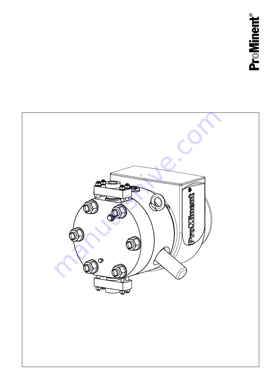
Hydraulic diaphragm liquid ends with PTFE dia‐

phragm
Orlita

®

 Evolution

Operating instructions

Serial no. .............................
These operating instructions form part of an operating manual and are only valid if used in conjunction with the documents

in this operating manual.

EN

983747

BA ORL 007 06/16 EN

Please carefully read these operating instructions before use. · Do not discard.

The operator shall be liable for any damage caused by installation or operating errors.

The latest version of the operating instructions are available on our homepage.

Summary of Contents for Orlita Evolution

Page 1: ...al and are only valid if used in conjunction with the documents in this operating manual EN 983747 BA ORL 007 06 16 EN Please carefully read these operating instructions before use Do not discard The...

Page 2: ...quire ments 28 7 4 Changing the hydraulic oil 29 7 5 Changing Gear Oil in a Power End Drive 33 8 Repairs 35 8 1 Dismantling the Diaphragm 35 8 2 Installing the Diaphragm 37 8 3 Dismantling the suction...

Page 3: ...g high voltage Warning hot surface Warning danger zone n Only use the hydraulic liquid end to meter or pump liquid feed chemicals n Only use the hydraulic liquid end after it has been correctly instal...

Page 4: ...have a thorough knowledge of oscillating metering pumps In areas at risk from explosion ATEX qualified person ATEX elec trical technician Hydraulic installation Technical personnel Service Electrical...

Page 5: ...with the relevant standards and regulations The electrical technician with an additional explo sion protection qualification can work on electrical systems and independently recognise and avoid possib...

Page 6: ...untry and every type of application nor to being unconditionally up to date WARNING Only use ATEX pumps in areas at risk from explosion Note the relevant regulations for the installation and operation...

Page 7: ...sure in the liquid end and adjacent parts of the system Disconnect the pump from the mains power supply and ensure that it cannot be switched on again by unauthorised persons Depressurise the system...

Page 8: ...to create the legal framework for the safe operation of the system or system component such as for example the preparation of operating instructions operator s duties When using the hydraulic liquid e...

Page 9: ...from the mains voltage Make sure that all protective equipment is refitted during operation Small amounts of hydraulic oil can evaporate out of the vent screws We recommend that you slightly ventilate...

Page 10: ...l damage The unit can be damaged or oil may escape due to incorrect or improper storage or transportation The unit should only be stored or transported in a well packaged state preferably in its origi...

Page 11: ...volution Data Sheet A B C D P_PZ_0018_SW Fig 1 Position of slings EF1a and EF2a A Single pump with motor B Single pump without motor C Single pump with motor D Single pump without motor Storage Transp...

Page 12: ...B C D P_PZ_0013_SW svg Fig 2 Position of slings EF3a and EF4a A Single pump with motor B Single pump without motor C Single pump with motor D Single pump without motor Storage Transport and Unpacking...

Page 13: ...d pressure equalisation required n Increase the oil level in the turrets only to the lower edge of the cast reinforcing stays only to the lower edge see Do not replace the vent screw by a stopper scre...

Page 14: ...oil change intervals are not extended by the stoppage time n Lower the oil level of the drive unit and the turrets to the oper ating level Otherwise there will be no thermal cut off with over pressur...

Page 15: ...ering pump Evolution from overloading It does not protect the system The diaphragm position control with supplementary leakage func tion makes sure that the diaphragm returns again and again to the ne...

Page 16: ...tools WARNING Danger of fire with flammable feed chemicals Combustible media may only be transported using stainless steel dosing heads Metering pumps can be used for metering flam mable media but fu...

Page 17: ...several times more than the permissible pressure of the system or the metering pump This could lead to lines bursting resulting in dangerous consequences with aggressive or hazardous feed chemicals I...

Page 18: ...incorrect use of the pressure relief valve The pressure relief valve can only protect the motor and the gear and then only against impermissible excess pressure caused by the metering pump itself It c...

Page 19: ...N Danger resulting from rupturing hydraulic components Hydraulic components can rupture if the maximum per missible operating pressure is exceeded Never allow the metering pump to run against a closed...

Page 20: ...tion B with pulsation damper 1 Main line 2 Storage tank Symbol Explanation Symbol Explanation Metering pump Foot valve with filter meshes Injection valve Level switch Multifunctional valve Manometer L...

Page 21: ...5 Installation Electrical see Operating Instructions for the Metering Pump Drive Unit Orlita Evolution Installation Electrical 21...

Page 22: ...6 Start Up see Operating Instructions for the Metering Pump Drive Unit Orlita Evolution Start Up 22...

Page 23: ...ot come into contact with oxygen WARNING It is mandatory that you read the safety information and specifications in the Storage Transport and Unpacking chapter prior to shipping the pump CAUTION Warni...

Page 24: ...f the safety instructions in its operating instructions Should external fans servomotors or other auxil iary equipment be installed these should also be disconnected and checked that they are voltage...

Page 25: ...nit covering between one quarter and three quarters of the oil inspection window 020 n With stopped pump and 0 stroke length When measured with the dipstick 525 of each turret does the oil level at th...

Page 26: ...on power end if necessary Wear test see documen tation on torsionally flexible claw couplings n Are the fixing bolts tight n Do the discharge valves suction valves and the pressure relief valve 358 d...

Page 27: ...see chapter Chapter 7 Maintenance on page 23 and the following Remove water and deposits if necessary n Clean the entire pump see Chap Chapter 7 2 Cleaning on page 28 n Rectify any paint damage n Repl...

Page 28: ...ture 120 C Max flushing duration at 120 C 15 min 7 3 Material Required Equipment Oil Change Requirements n Types of oil refer to the Operating oils and lubricants hydraulic diaphragm pumps Evolution d...

Page 29: ...NING The oil drainage plug turret oil and other pump com ponents can become very hot Allow the pump to cool down or Take appropriate protective measures CAUTION Feed chemical can enter the hydraulic o...

Page 30: ...70 B0837 Fig 8 Oil drainage plug with sealing ring 570 EF1a and EF2a B0850 570 580 Fig 9 Oil drainage plug with sealing ring EF3a 570 and EF4a 580 2 Place an oil trough under the turret Maintenance 30...

Page 31: ...c oil runs out of the diaphragm holder 300 6 Screw the oil drainage plug with sealing ring into the turret Use a new oil drainage screw with sealing ring 570 if neces sary 7 Screw the pressure relief...

Page 32: ...nspection window 336 and the bleed valve 356 from the diaphragm holder 300 3 Only EF1a EF2a and EF3a Fill hydraulic oil through the opening for the bleed valve 356 until the diaphragm holder 300 is fi...

Page 33: ...e sure that the oil level is between Minimum end of the dipstick and Maximum marking WARNING The pump can become too hot If too much oil is filled the internal cooling system cannot draw in any more c...

Page 34: ...on the oil drainage plug 060 Is the seal 065 still ok 2 Remove the vent screw 015 from the power end drive 3 Slowly fill gear oil through the opening 4 Is the gear oil covering up to quarter full to...

Page 35: ...phragm WARNING The oil drainage plug turret oil and other pump com ponents can become very hot Take appropriate protective measures or Allow the pump to cool down CAUTION Hydraulic oil can escape duri...

Page 36: ...8 with protective cap 363 3 Unscrew the pressure relief valve 358 from the diaphragm holder 300 The hydraulic oil runs out of the diaphragm holder 300 B0811 Fig 14 4 Loosen the hexagonal nuts 332 and...

Page 37: ...the Diaphragm The lifetime of the diaphragm can be increased by installing the finished diaphragm assembly 101 into the liquid end at the temperature that the feed chem ical will subsequently have Ma...

Page 38: ...be longer the less the diaphragm assembly 101 is now mechanically stressed 2 Clean all sealing surfaces for the diaphragm assembly 101 on the dosing head 100 and the back plate the diaphragm holder 3...

Page 39: ...pin screws of the dia phragm holder 300 7 Place the washers on the pin screw and grease the thread B0811 Fig 19 8 Screw the hexagonal nuts 332 onto the pin screws and tighten manually Tighten the hex...

Page 40: ...CAUTION Minimum waiting time between levels 2 min 8 3 Dismantling the suction valve and discharge valve WARNING The valves feed chemical and other pump compo nents can become very hot Take suitable s...

Page 41: ...e mains power supply The diaphragm holder is thus also depressurised B0814 Fig 21 2 Loosen the hexagonal nuts and remove the screw connector There is no need for a screw connector 200 because of the s...

Page 42: ...section drawing cleanly into the upper hole of the dosing head 3 Carefully position the screw connector CAUTION Make sure that the seal between the valve housing and the screw connector is clean 4 Pl...

Page 43: ...tective measures or Allow the pump to cool down CAUTION The bleed valve 356 is pre set and should only be fully replaced Materials required n Open end wrench 1 Only depressurise the discharge line whe...

Page 44: ...e 358 is pre set and should only be fully replaced Materials required n Oil trough n Open end wrench 1 Only depressurise the discharge line when the pump is run ning Then disconnect the pump from the...

Page 45: ...ion sparks Consider potential equalisation before you approach any pump equipment that could be at a different electrical potential such as pipes or tools WARNING Danger of an electric shock Personnel...

Page 46: ...sure Remove dirt technical personnel Dosing head insuffi ciently filled Fill the dosing head technical personnel Hydraulic oil level too low Top up with hydraulic oil Instructed person Pump does not...

Page 47: ...too large falls below minimum required suction pressure On the suction side remove dirt check shut off valves and check the design of the suction side pipework technical personnel Pump meters too lit...

Page 48: ...l personnel Leakage at the inner clamping points of the diaphragm Replace diaphragm assembly tighten clamping screw check O ring on diaphragm mounting plate and if necessary replace turn diaphragm ass...

Page 49: ...in the Storage Transport and Unpacking chapter is read before shipping or transporting the unit Thoroughly clean the liquid end and the housing of chemicals and dirt Adhere to the material safety dat...

Page 50: ...hapter Storage Transport and Unpacking Preservation Personnel n Technical personnel 1 Disconnect the pump from the mains power supply 2 Depressurise and bleed the hydraulic system around the pump 3 Fl...

Page 51: ...nd drive the liquid ends and hydraulic ends that could cause environ mental damage Drain the oil from the pump Note the local guidelines currently applicable in your country CAUTION Refer to the docum...

Page 52: ...ter 19 Functional description 15 G General overhaul 27 I Information in the event of an emergency 8 Inspections 25 Installation 16 Installation Electrical 21 Installation Hydraulic 16 Installing the b...

Page 53: ...53...

Page 54: ...54...

Page 55: ...55...

Page 56: ...Heidelberg 4 en_GB 2015 ProMinent GmbH Im Schuhmachergewann 5 11 69123 Heidelberg Germany Germany Telephone 49 6221 842 0 Fax 49 6221 842 419 Email info prominent com Internet www prominent com...

Reviews: