ProMinent mikro delta Operating Instructions Manual Download Page 1

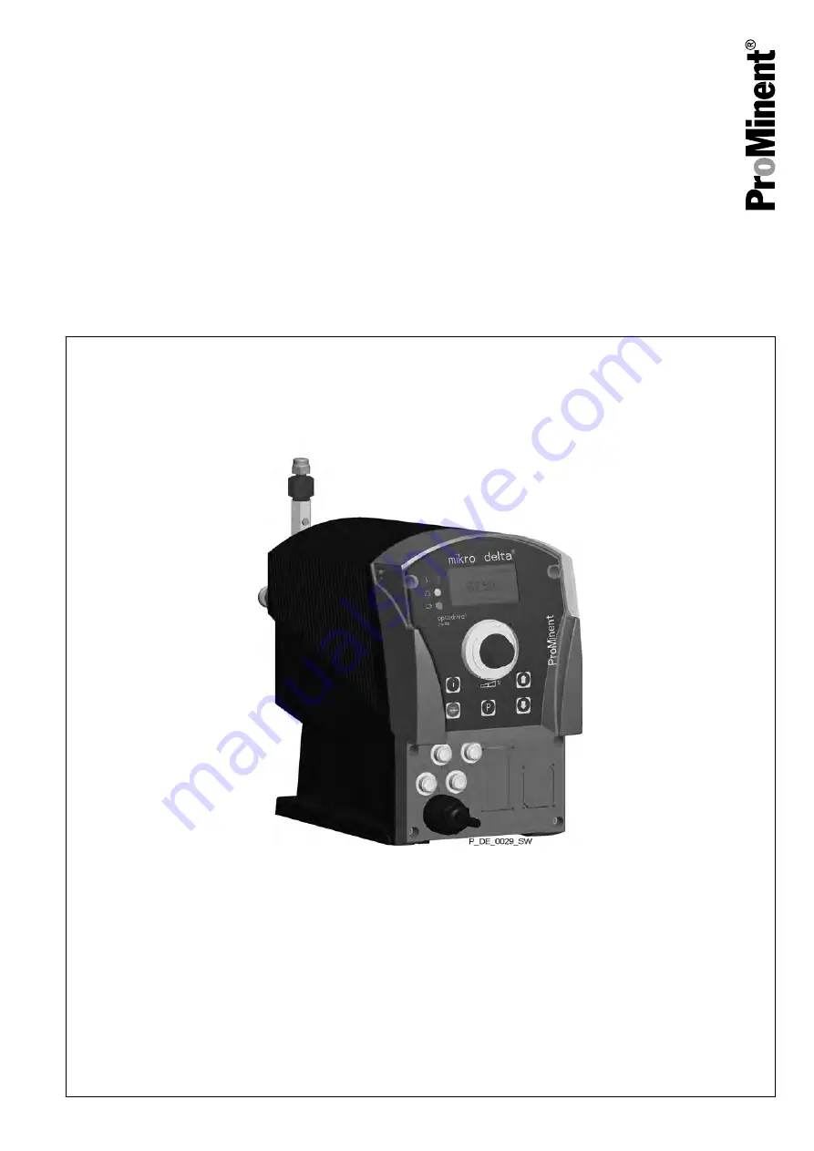
Precision Piston Metering Pump
mikro delta

®

 MDLa

Operating instructions

with controlled optoDrive

®

 solenoid drive

Original Operating Instructions (2006/42/EC)

Part no. 986160

BA DE 024 08/12 EN

Please carefully read these operating instructions before use! · Do not discard!

The operator shall be liable for any damage caused by installation or operating errors!

Technical changes reserved.

ООО

 "

ПромХимТех

официальный


партнер


и


поставщик


насосов

 ProMinent                                     

www.promhimtech.ru / [email protected]

Summary of Contents for mikro delta

Page 1: ...ginal Operating Instructions 2006 42 EC Part no 986160 BA DE 024 08 12 EN Please carefully read these operating instructions before use Do not discard The operator shall be liable for any damage cause...

Page 2: ...Please read these operating instructions carefully before use Do not discard Please state identity code and serial number which you can find on the nameplate when you contact us or order spare parts T...

Page 3: ...ector 29 9 2 Description of the jacks 30 9 2 1 External control terminal 30 9 2 2 Level Switch terminal 31 9 2 3 Dosing monitor terminal 31 9 3 Relay 32 9 3 1 Fault indicating relay output identity co...

Page 4: ...acing liquid end parts 63 14 Troubleshooting 67 14 1 Faults without a fault alert 67 14 2 Fault alerts 68 14 3 Fault alerts warning alerts 68 14 4 Warning Alerts 69 14 5 All Other Faults 69 15 Decommi...

Page 5: ...seals pure white G PTFE seals graphite Dosing head version 0 Without bleed valve without valve spring 1 Without bleed valve with valve spring Hydraulic connection 0 Standard connection in line with te...

Page 6: ...es 0 No accessories Control versions 0 Manual external contact with pulse control 3 Manual external contact with pulse control analog 0 4 20mA 4 As 0 14 day process timer 5 As 3 14 day process timer C...

Page 7: ...emical n Continuous stroke length adjustment from 0 100 n Adjustment and display of the feed rate either as strokes min strokes h or l h via the keyboard n Large illuminated graphic display n External...

Page 8: ...o dose liquid metering chemicals n The pump may only be started up after it has been correctly installed and commissioned in accordance with the technical data and specifications contained in the oper...

Page 9: ...pair WARNING Warning of crushing of the fingers The moving parts in the turret can crush fingers The protective bush on the liquid end must always be closed when the pump is ready for operation WARNIN...

Page 10: ...e product equipment catalogue under www prominent com CAUTION Warning of feed chemical spraying around The metering pump can generate a multiple of its rated pressure If a discharge line is blocked hy...

Page 11: ...pump by pressing the Stop Start key If necessary depressurise the hydraulic system around the pump Observe the safety data sheet for the feed chemical Activity Qualification level Storage transport u...

Page 12: ...technicians must comply with the provisions of the appli cable statutory directives on accident prevention Instructed person An instructed person is deemed to be a person who has been instructed and...

Page 13: ...integral part of an inspection repair order A unit can only be inspected or repaired when a Declaration of Decontamination Form is sub mitted that has been completed correctly and in full by an autho...

Page 14: ...95 rel humidity non condensing Compare the delivery note with the scope of supply n Metering pump with mains power cable n Connector kit for hose pipe connection n Edge pin TT_ only n Product specifi...

Page 15: ...1 2 3 P_DE_0005_SW Fig 2 1 Control unit 2 Drive unit 3 Liquid end 1 5 6 2 3 4 P_DE_0028_SW Fig 3 1 Back pressure valve 2 Vent screw 3 Discharge valve 4 Suction valve 5 Protective bush 6 Threaded hole...

Page 16: ...l Switch jack 14 Diaphragm rupture reporter jack 15 Optional module slot timer PROFIBUS CAN Bus 16 Relay and mA output option 5 2 1 Key functions Key Application In continuous displays operation In ad...

Page 17: ...of a selection effect similar to an ESC key Pressed simultane ously Suction in continuous display Stroke rate 5 2 2 Stroke length adjustment knob The stroke length can be adjusted using the stroke le...

Page 18: ...the value set at the time of the last locking of the adjustment menu Level The Warning level in the storage tank was under shot If the symbol flashes the level has fallen below the Fault level in the...

Page 19: ...eband The pump is in operating mode Analog The processing type Curve Upper sideband is set Lower sideband The pump is in operating mode Analog The pro cessing type Curve Lower sideband is set The pump...

Page 20: ...ain cause for imprecise metering with high viscosity feed chemi cals namely the incomplete filling of the liquid end For the case of gaseous feed chemicals the slow suction stroke prevents cavita tion...

Page 21: ...ernal control jack Processing of the current signal can be pre selected via the control unit 6 5 Functions The following functions can be selected vin the menu Settings The stroke rate is controlled u...

Page 22: ...ot refer to Retrofitting relays This combined relay can generate a contact with each stroke via its pacing relay in addition to its function as a fault indicating relay The relay can be retrofitted th...

Page 23: ...e pump has performed a stroke It starts to flash as soon as the stroke rate falls below 30 strokes min 6 10 Hierarchy of operating modes functions and fault statuses The different operating modes func...

Page 24: ...ue to incorrect operation and poor maintenance Ensure that the pump is accessible at all times Adhere to the maintenance intervals Capacity too low The liquid end valves can be disrupted by vibrations...

Page 25: ...TION Warning of backflow A back pressure valve or a spring loaded injection valve do not represent absolutely leak tight closing ele ments For this purpose use a shut off valve a solenoid valve or a v...

Page 26: ...ery to approx 60 80 Do not kink the hose in the following step To press on use e g anti skid emery paper or sim ilar 3 Press the hose with the screw fitting and the slide ring onto the hot edge pin Da...

Page 27: ...16 Preparation Remove the hose with the nipple from the liquid end 1 Push the connecting nut thrust collar and the tensioning collar onto the pipe 2 Push the pipe end right into the hole 3 Place the...

Page 28: ...ed from the mains Install an emergency cut off switch in the pump power supply line or Integrate the pump in the emergency cut off man agement of the system and inform personnel of the isolating optio...

Page 29: ...nically correctly and in accordance with the operating instructions and applicable regulations 9 1 Supply voltage connector WARNING Unexpected startup is possible As soon as the pump is connected to t...

Page 30: ...in 3 mA output identity code character istic Control variant 3 5 and R 1 Data Value Unit Input apparent ohmic resistance approx 120 1 The metering pump makes its first metering stroke at approx 0 4 mA...

Page 31: ...vel Switch terminal There is a connecting option for a 2 stage level switch with pre warning and limit stop Electrical interface Data Value Unit Voltage with open contacts 5 V Input resistance 10 k Co...

Page 32: ...relay works when there are fault alerts from the pump and in the event of the Liquid level low 2nd stage fault alert The fault indicating relay can be retrofitted and is operational once attached to t...

Page 33: ...n be retrofitted and is opera tional once attached to the relay board refer to Retrofitting Relays in the Appendix Electrical interface for semiconductor switch pacing relay Data Value Unit Maximum re...

Page 34: ...if no entry has been started flashing beam You will jump back to the previous menu point or menu at most back to the main menu Press and hold the P key for 3 seconds Entry is cancelled and you jump ba...

Page 35: ...Keep key i pressed down until a small arrow appears and glides into the bottom line of the LCD display 3 As soon as it has reached it quickly release the i key and immediately page through the info d...

Page 36: ...lected n Manual for manual operation n Batch for batch operation n Contact for contact operation n Analog for current control P P Continuous display P Main Analog Mode Settings Security Clear P Mode A...

Page 37: ...Menu Profibus Menu Auxiliar Menu Calibration Submenu Info Submenu Change head Menu Dosing Menu Flow Menu Relay Menu Analog Out Menu System Main Mode Settings Security Clear Analog Menu Settings Fig 2...

Page 38: ...ontrol jack The number of received pulses which could not yet be processed is stored by the pump in the stroke memory CAUTION When changing over from the Manual operating mode to the Batch operating m...

Page 39: ...strokes CAUTION When changing over from Manual operating mode to Contact operating mode the pump maintains the stroke rate The stroke rate can also be set in Contact operating mode It should normally...

Page 40: ...n With a factor of 1 1 stroke is executed per 1 pulse With a factor of 0 5 1 stroke is executed after 2 pulses With a factor of 0 1 1 stroke is executed after 10 pulses With a factor of 0 75 1 stroke...

Page 41: ...u on page 44 in Analog operating mode in the Settings menu the ANALOG menu is also available The stroke rate is controlled using an analog current signal via the External control terminal The continuo...

Page 42: ...s Analog Analog Concentration Auxiliar Calibration P Main Analog Mode Settings Security Clear P Curve Analog Straight top side band bottom Sideband 0 20 0 20 0 20 0 20 P top side band Analog I1 04 0mA...

Page 43: ...ow The Lower sideband symbol appears in the LCD display Below I1 the pump works at a rate of F1 above I2 it stops Between I1 and I2 the stroke rate varies between F1 and F2 in proportion to the signal...

Page 44: ...n be activated via the External control terminal If the auxiliary rate applies then the identifier Aux appears in the LCD display This auxiliary rate has priority over the stroke rate which is speci f...

Page 45: ...ion The calibration will not be accurate if these conditions are not adhered to do not allow the stroke length to fall below 10 The pump should execute at least 100 strokes P P P P P Continuous displa...

Page 46: ...s to pump and indicates the stroke rate the pump works at the stroke rate which is set under MANUAL 10 After a reasonable number of strokes e g 100 stop the pump by pressing the P key 11 Determine the...

Page 47: ...suction stroke leads to a lower capacity In both metering modes it is possible to selectively also slow the suction stroke For the case of volatile feed chemicals the slow suction stroke prevents cav...

Page 48: ...silicone oil Newtonian liq uids with a 0 5 m suction line For the adjustment for slowing the suction stroke dependent upon the feed chemical viscosity see the Adjustment chapter 10 6 5 Settings for t...

Page 49: ...switch due to a trig gering event from the timer upon a warning alert a fault alert or a pump stroke Selectable behaviour types Setting in the Relay menu Effect Warning The relay switches upon a warn...

Page 50: ...0mA P Settings Batch Dosing Relay Analog Out System P Main Batch Mode Settings Security Clear Continuous display P 0 20mA Batch h ml h x Capacity P Capacity Batch 186 ml h at 20 mA only under Capacity...

Page 51: ...llowing sub menus n Info n Change head 10 6 7 1 Info sub menu In the Info sub menu you can read off the following identification numbers n Identity code ID n Serial number SN n Software control SW n H...

Page 52: ...g setting dia gram in the appendix in addition to the adjustment mode In the next menu option enter the number you want to use as the code If a lock is set a padlock appears in the continuous display...

Page 53: ...r of strokes n Quantity total litres n all both To do this quit the menu by quickly pressing the key P key The variables have increased since commissioning of the pump the last calibration or the last...

Page 54: ...ING Danger of electric shock A mains voltage may exist inside the pump housing If the pump housing has been damaged you must disconnect it from the mains immediately It may only be returned to service...

Page 55: ...length adjustment knob and the use of the locking lever A B P_DE_0023_SW 0 0 33 0 33 2 100 0 Fig 25 Adjustment examples for stroke length values 0 00 33 0 33 2 and 100 0 Locking lever in position A s...

Page 56: ...menu for Lock all then after pressing the P key the access code must first be entered The directly changeable variables are in detail In operating modes Manual Contact and Batch You can change the st...

Page 57: ...rity lock Lock all Priming Start batch only in Batch operating mode Acknowledge error Check adjustable variables Fig 26 Operating options with a locked operating menu 11 2 Remote operation There is an...

Page 58: ...rts Interval Maintenance work Personnel Quarterly n Check the condition of the sealing sleeves see the Overhaul chapter n Check that the dosing lines are fixed firmly to the liquid end n Check that th...

Page 59: ...Fig 27 Leakage hole Maintenance 59...

Page 60: ...hemical are uncovered and handled during overhaul work Protect yourself from the feed chemical should it be hazardous Read the safety data sheet on the feed chemical CAUTION Warning of feed chemical s...

Page 61: ...at pin or similar into the smaller hole of the dis charge connector and push the valve inserts out of it 3 Inspect all parts for damage before assembling 4 After cleaning the valve first screw it on f...

Page 62: ...seals in the dosing head and valves which may possibly have to be renewed n The flow direction of the suction connector is the opposite of that of the discharge connector 1 Inspect all parts for damag...

Page 63: ...024_SW Fig 28 2 Turn the stroke adjustment knob until it can go no further with 0 stroke length if the pump is running the drive axle is then blocked 3 Switch off the pump 4 Unscrew the hydraulic conn...

Page 64: ...ure plate 3 Shim 4 Disc springs 5 Friction washer 6 Screws 7 Piston Type 100150 A A A P_DE_0038_SW TTT TTG SST SSG Fig 30 Arrangement and dimension A for the disc springs 1 Insert the V sleeve set 1 w...

Page 65: ...nd do not overtighten 7 Carefully insert the piston 7 If the liquid end is to be stored this is the correct condition 8 Screw the screws 6 on to the friction washer 5 with the piston 7 inserted Tighte...

Page 66: ...s 11 2 Push on the dosing head 3 Tighten the knurled screws 9 The liquid end is now secured Piston fracture risk Do not tilt the piston in the step described here 4 Snap the coupling disc 8 on to the...

Page 67: ...Pump does not prime in spite of full stroke motion and bleeding Minor crystalline deposits on the ball seat due to the valves drying out Take suction tube out of the storage container and thoroughly...

Page 68: ...D indicator illuminates the symbols m and External flashes in the LCD display the Fault and Stop symbols are also displayed and the pump stops The stroke memory has overflown Rectify the cause then pr...

Page 69: ...Electrician The dosing monitor reported too few strokes more that set in the FLOW menu press the P key Investigate and clear the cause Technical personnel 14 4 Warning Alerts Fault description Cause R...

Page 70: ...end before working on the pump CAUTION Warning of feed chemical spraying around Feed chemical can spray out of the hydraulic compo nents if they are manipulated or opened due to pres sure in the liqui...

Page 71: ...e that it cannot be switched on again by unauthorised persons Depressurise the system before commencing any work on hydraulic parts Personnel n Technical personnel CAUTION Environmental hazard due to...

Page 72: ...ar 100150 TT 1 75x1 15 6 0 6 5 2 5 100600 TT 1 75x1 15 6 2 0 5 2 5 101500 TT 3 2x2 4 4 2 0 5 1 5 600150 SS 1 75x1 15 1 58 6 0 6 30 2 5 400600 SS 1 75x1 15 1 58 6 2 0 20 2 5 201500 SS 3 2x2 4 3 18 4 2...

Page 73: ...TG PTFE carbon PTFE carbon Jewel Ceramic Ceramic PTFE PTFE graphite SST Stainless steel 1 4571 Stainless steel 1 4571 Jewel Ceramic Ceramic PTFE PTFE white SSG Stainless steel 1 4571 Stainless steel 1...

Page 74: ...dependent on the ambient and feed chemical temperatures 16 6 Climate Data Value Unit Maximum air humidity 95 rel humidity non condensing Exposure in a humid and alternating climate FW 24 according to...

Page 75: ...ight kg TT_ 10 SS_ 11 16 9 Sound pressure level Sound pressure level LpA 70 dB in accordance with EN ISO 20361 2010 10 at maximum stroke length maximum stroke rate maximum back pressure water Sound pr...

Page 76: ...dimensions in mm Material ver sions TT A B C D E 100150 243 9 150 1 105 1 159 1 49 100600 243 9 150 1 105 1 159 1 49 101500 256 2 150 1 92 3 161 1 49 Material ver sions SS A B C D E 600150 256 2 150 1...

Page 77: ...30 40 50 60 70 80 90 100 100 min 1 50 min 1 40 min 1 30 min 1 20 min 1 10 min 1 90 min 1 80 min 1 70 min 1 60 min 1 100 f 90 80 70 60 50 40 30 20 10 C ml h MDLa 100150 s A 0 100 200 300 400 500 600 0...

Page 78: ...00 min 1 50 min 1 40 min 1 30 min 1 20 min 1 10 min 1 90 min 1 80 min 1 70 min 1 60 min 1 100 f 90 80 70 60 50 40 30 20 10 C ml h MDLa 600150 s A 0 100 200 300 400 500 600 0 10 20 30 40 50 60 70 80 90...

Page 79: ...8 127 125 126 124 121 122 118 149 148 114 113 115 116 117 111 151 136 142 146 143 141 138 140 137 110 112 144 145 116 118 P_DE_0036_SW Fig 35 Liquid end mikro delta 100150 101500 TT Liquid end mikro d...

Page 80: ...22 121 120 111 112 149 148 110 138 136 137 140 144 145 142 141 143 146 111 116 117 115 113 114 116 118 127 151 116 118 P_DE_0035_SW Fig 36 Liquid end mikro delta 600150 201500 SS Liquid end mikro delt...

Page 81: ...kro T 110 C D 1 000 Dosierkopf d5 0 mikro T Dosing head d5 0 mikro T 110 E F 1 000 Dosierkopf d8 0 mikro T Dosing head d8 0 mikro T 111 A D 1 000 Anschlu st ck Saugseite PTFE Connection suction side P...

Page 82: ...d5 Graphit PTFE collar set d5 graphite 136 E 1 000 PTFE Mansch Satz d8 PTFE wei PTFE collar set d8 PTFE white 136 F 1 000 PTFE Mansch Satz d8 Graphit PTFE collar set d8 graphite 137 A B 1 000 Drucktel...

Page 83: ...pf d5 0 MG5a S Dosing head d5 0 MG5a S 110 E F 1 000 Dosierkopf d8 0 MG5a S Dosing head d8 0 MG5a S 111 A D 1 000 Anschlu st ck UNF 10 32 S Connection UNF 10 32 S 111 E F 2 000 Anschlu st ck UNF 5 16...

Page 84: ...PTFE Mansch Satz d5 Graphit PTFE collar set d5 graphite 136 E 1 000 PTFE Mansch Satz d8 PTFE wei PTFE collar set d8 PTFE white 136 F 1 000 PTFE Mansch Satz d8 Graphit PTFE collar set d8 graphite 137 A...

Page 85: ...e on the unit Applicable EC Machinery Directive 2006 42 EC EC Directives EC EMC Directive 2004 108 EC The safety objectives of the Low Voltage Directive 2006 95 EC were complied with in accordance wit...

Page 86: ...22 Decontamination declaration Decontamination declaration 86...

Page 87: ...Menu Settings P P Main Analog Mode Settings Security Clear P P P i STOP START Continuous display 2 s Pump stop start Change directly alterable variables Priming Start batch only in Batch operating mod...

Page 88: ...Menu Security Menu Clear Menu Language Operating adjustment overview 88...

Page 89: ...isplay External Factor Identifier m only should function extension Stroke memory be activated with the arrow keys Up and Down directly alterable variables 86500 Manual 6000 h 86500 Manual 100 min 8650...

Page 90: ...e rate Strokes min Capacity Factor Total litres Dosing amount Stroke length Signal current at the input Dosing mode Total strokes Batch size Remaining litres Remaining strokes 1 only after running thr...

Page 91: ...ction 74 Device overview 15 Discharge stroke 20 47 Discharge valve 15 Disposal 71 Dosing head 63 Dosing monitor 31 E Emergency 11 Emptying the liquid end 70 Explanation of the safety instructions 8 Ex...

Page 92: ...ur 48 Remote operation 57 Reproducibility 20 S Safety chapter 8 Safety declaration form 13 Safety requirements 74 Scope of supply 14 Secondary displays 35 SECURITY 52 Semiconductor switch 33 Serial nu...

Page 93: ...93...

Page 94: ...94...

Page 95: ...95...

Page 96: ...Minent Dosiertechnik GmbH Im Schuhmachergewann 5 11 69123 Heidelberg Germany Telephone 49 6221 842 0 Fax 49 6221 842 617 email info prominent com Internet www prominent com ProMinent www promhimtech r...

Reviews: