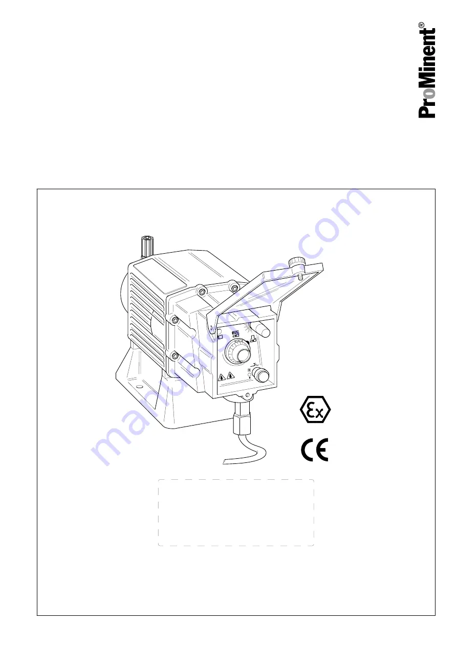
ProMinent EXtronic EXBb Operating Instructions Manual Download Page 1

Metering pump
ProMinent EXtronic

®

 EXBb

Operating instructions

0158

EN

Original operating instructions (2006/42/EC)

Part No. 987094

BA EX 0 16 09/19 EN

Please carefully read these operating instructions before use. · Do not discard.

The operator shall be liable for any damage caused by installation or operating errors.

The latest version of the operating instructions are available on our homepage.

Summary of Contents for EXtronic EXBb

Page 1: ...ctions 2006 42 EC Part No 987094 BA EX 0 16 09 19 EN Please carefully read these operating instructions before use Do not discard The operator shall be liable for any damage caused by installation or operating errors The latest version of the operating instructions are available on our homepage ...

Page 2: ...ys Information This provides important information relating to the correct operation of the unit or is intended to make your work easier Safety Information Safety information is identified by pictograms see Safety Chapter These operating instructions conform to current EU regulations applicable at the time of publication Please state identity code and serial number which you can find on the namepl...

Page 3: ...al 27 9 Start up 31 9 1 Determining pump capacity 33 9 2 Setting the pump capacity 34 10 Troubleshooting 36 11 Maintenance 38 12 Repair 40 12 1 Replacing metering diaphragm 40 12 2 Checking diaphragm rupture sensor 42 12 3 Replacing separating diaphragm of the diaphragm rupture sensor 43 12 4 Installing dosing head 43 13 Decommissioning and disposal 45 13 1 Decommissioning 45 13 2 Disposal 46 14 T...

Page 4: ...17 Ordering information for fuses 66 18 Declaration of Conformity 68 19 Index 69 Table of contents 4 ...

Page 5: ...ings flat seal PTFE SS2 Stainless steel 1 4571 with internal thread1 4 NPT seal PTFE SB1 Stainless steel 1 4571 with internal thread Rp 1 4 or 1 2 SSM As SS1 with diaphragm rupture sensor SBM As SB1 with diaphragm rupture sensor Valve spring 0 With valve spring 1 With 2 valve springs 1 4571 0 1 bar Electrical connection A 230 V 50 60 Hz open end B 115 V 50 60 Hz open end C 200 V 50 60 Hz open end ...

Page 6: ...ol version 0 with potentiometer 1 with push button for maximum frequency 2 with push button switch over for maximum frequency Certification voltage language 0 BVS Europe 100 500 V German 1 BVS Europe 100 500 V English 2 FM USA 115 V English 3 CSA Canada 115 V 230 V English Identity code 6 ...

Page 7: ...plosion group category and degree of protection specified on the label must corre spond to or be better than the conditions in the intended appli cation n The pump may only be used after it has been correctly installed and started up in accordance with the technical data and specifications contained in the operating instructions n Observe the general limitations with regard to viscosity limits che...

Page 8: ...ed to them and recognise possible dangers based on their technical training knowledge and experience as well as knowledge of pertinent regulations Note A qualification of equal validity to a technical qualification can also be gained by several years of employment in the relevant field of work Electrical technician with knowledge of explosion protection An electrical technician with an additional ...

Page 9: ...ical be used It may escape from the hydraulic components when working on the pump When pumping flammable media the operator must take suitable safety precautions WARNING Danger from hazardous substances Possible consequence Fatal or very serious inju ries Please ensure when handling hazardous sub stances that you have read the latest safety data sheets provided by the manufacture of the haz ardous...

Page 10: ...maintenance The metering behaviour of the pump changes if a different liquid end size is fitted Only ProMinent Service may open the housing Adhesive labels WARNING The following safety information must be affixed to pumps that contain parts made of electrically non conducting plastic Ensure that the label is always fitted and legible The label should indicate that plastic parts may only be wiped d...

Page 11: ...in line with the emergency shut down guidelines for your system If feed chemical escapes also ensure that the pump s hydraulic environment is at atmospheric pressure Adhere to the material safety data sheet for the feed chemical Sound pressure level LpA 70 dB according to EN ISO 20361 at maximum stroke length maximum stroke rate maximum back pressure water Information in the event of an emer gency...

Page 12: ...ed person on behalf of the pump oper ator The Decontamination Declaration Form can be found on our homepage CAUTION Danger of material damage The device can be damaged by incorrect or improper storage or transportation The unit should only be stored or transported in a well packaged state preferably in its original packaging The packaged unit should also only be stored or transported in accordance...

Page 13: ...4 Overview of equipment 1 2 3 4 5 6 7 8 9 12 14 15 13 11 16 10 17 Overview of equipment 13 ...

Page 14: ...417 NP and PP types 7 Suction connector 8 Nameplate 9 Operating display 10 Inspection window stroke length control knob 11 External connection 12 Mains connection 13 Mains switch not for 500 V version 14 Stroke length control knob 15 Locking lever 16 Control knob for stroke rate or pushbutton pushbutton switch for priming 17 Transparent cover Overview of equipment 14 ...

Page 15: ...pleted 5 3 Self Bleeding Self bleeding liquid ends SEK types are capable of independent priming when a discharge line is connected and diverting existent air pockets via a bypass During operation they are also capable of conveying away gases which are produced independently of the operating pressure in the system It is also possible to dose pre cisely in a depressurised state due to the integral b...

Page 16: ...ly 2 bar system back pres sure is an electrical signal triggered in the event of diaphragm rupture CAUTION Once the operating membrane has ruptured a pre cise metering rate can no longer be guaranteed 5 5 Metering rate The stroke length can be continuously adjusted between 100 and 10 using the stroke length control knob 14 The stroke rate control knob 16 can be used to manually set 0 to 110 120 st...

Page 17: ...As for Internal stroke rate setting version however there is also the possibility of switching the metering on and off via an external semiconductor contact or potential free contact All control types that can be controlled via an input can be supplied with an External control input of a non intrinsically safe i a or intrinsi cally safe type 5 7 Button for maximum stroke rate Identity code charact...

Page 18: ... can arise from a poorly accessible pump due to incorrect operation and poor maintenance Ensure that the pump is accessible at all times Adhere to the maintenance intervals Capacity too low The liquid end valves can be disturbed by vibra tions Secure the metering pump so that no vibra tions can occur Capacity too low If the valves of the liquid end are not vertical they cannot close correctly Suct...

Page 19: ... chemicals Flammable media may only be transported using stainless steel dosing heads In excep tional cases where this is not possible PTFE with carbon can be used whereby our TT_ ver sions are manufactured from this conducting plastic Here the operator is urged to take spe cial care due to the low mechanical strength The metering pumps may meter flammable media but only in principle versions with...

Page 20: ... 0 3 mm Install a suitable filter in the suction line CAUTION Warning of the discharge line rupturing With a closed discharge line e g from a clogged discharge line or by closing a valve the pressure that the metering pump generates may reach sev eral times more than the permissible pressure of the system or the metering pump This could lead to lines rupturing resulting in dangerous conse quences ...

Page 21: ...Use a shut off valve a solenoid valve or a vacuum breaker for this purpose CAUTION Danger resulting from unnoticed diaphragm rup ture If the pump has been ordered with an electric dia phragm rupture sensor it still has to be installed Screw the enclosed diaphragm rupture sensor into the liquid end CAUTION Warning of unnoticed diaphragm rupture Only above approximately 2 bar system back pres sure i...

Page 22: ...r insert Adjustable back pressure valve also used as a relief valve Interim tank with float valve Multifunctional valve Level switch Shut off valve Manometer Solenoid valve Filling device Ball retaining valve Siphon device 7 2 Information on the suction side installation n Always use bends to curve lines never angles Key for all hydraulic diagrams Bends P_MAZ_0027_SW Fig 6 Installation hydraulic 2...

Page 23: ...valve at the end of the suction line in case the pump is higher than the maximum fluid level in the storage tank n Only shorten the free end of the suction line until the foot valve is suspended just above the container base 7 3 Information on the discharge side installation n Install a vacuum breaker if the feed chemical may not press through the metering pump Metering pumps are not absolutely le...

Page 24: ... Cause Remedy The suction line cannot be bled A pocket of air arrow is in the suction line Prevent the air pocket or install as shown in Ä Avoid exceeding maximum permissible oper ating pressure on page 24 Fault description Cause Remedy Feed chemical flows uncon trolled when the line is filled Siphon effect by dis charge line falling too deeply Interrupt the discharge line as in Ä With high suctio...

Page 25: ...rmissible operating pressure on page 24 The metering pump meters the feed chem ical in a cycle The overflow line is routed back into the suc tion line whereby it is possible that the multi functional valve no longer closes after being opened Install as in Ä Avoid exceeding maximum permissible operating pressure on page 24 7 5 Special installation instructions n Position the end of the discharge li...

Page 26: ... fluctuating pressure use an interim tank with a float valve to ensure a reg ular delivery flow n When metering into a main line in which there is negative pressure install a multifunctional valve a back pressure valve DHV RM or an injection valve in the discharge line to ensure that the feed chemical is not sucked through With high suction side pressure 3 P_MAZ_0015_SW Fig 19 With fluctuating suc...

Page 27: ... ancillaries which may possibly be present from the mains Install an emergency cut off switch in the mains supply line to the pump and any elec trical ancillaries which may be present or Integrate the pump and electrical ancillaries which may be present in the emergency cut off management of the system and inform per sonnel of the isolating option WARNING Danger of electric shock This pump is equi...

Page 28: ...onnection terminal for potential equalisation Tab 1 EXBbG L1 Phase Brown N Neutral blue PE Protective earth conductor Yellow green Tab 2 EXBbM L1 Phase Brown N Neutral grey free Black PE Protective earth conductor Yellow green internal isolated external connect to a free terminal twist the three individually concentric protective earth conductors together cover with yellow green hose and connect t...

Page 29: ...potential equalisation line is located on the housing next to the mains connection 12 Tab 3 Contact analogue and pause input not intrinsically safe EXBbG Input Black 1 Input Black 2 EXBbM Input blue Input black Tab 4 Contact analogue and pause input intrinsically safe i a sheath colour blue EXBbG Input Black 1 Input Black 2 EXBbM Input blue Input black 10 20 30 40 50 60 70 100 1 0 19 0 50 10 20 30...

Page 30: ...s of the Namur sensor to indicate a diaphragm rupture Tab 5 Electrical connection for diaphragm rupture sensor intrinsi cally safe i a sheath colour blue EXBbG and EXBbM Input Brown 1 Input Blue 2 When using flammable media WARNING Risk of fire with flammable feed chemicals Make sure that the electric diaphragm rupture sensor switches off the pump immediately after a diaphragm rupture Connect the ...

Page 31: ...ium through the suction connector Before setting the stroke length release the lock Only adjust the stroke length when the pump is running Completely reliable metering cannot be expected once the pump has come to a standstill which explains why the metering has to be checked regularly 1 Check that the pressure relief valves are working properly 2 Check that the pump connectors and connections are ...

Page 32: ...d valve Release the metering line or open the bleed valve 2 Switch on pump and vent with 100 stroke length with HV version Initial priming and bleeding is hampered by the fact that the valves and valve springs are still dry Therefore Use as short a priming lift as possible or for the feed priming pressure bleed on the suction side and liquid end If this doesn t help 1 Unscrew the pressure connecto...

Page 33: ...cross all material versions is 5 for maximum no details 1 Select the desired pump capacity from the value of ranges for the pump type see performance data 2 Select the nomograph and diagram of the pump type 3 On the diagram s X coordinate mark the back pressure in the metering system and read the associated correction factor off the X axis 4 Divide the desired pump capacity by the correction facto...

Page 34: ...eight and high rate for good mixing For precise metering wherever possible select a stroke length of no less than 30 at max imum pressure the stroke length should be 60 for type 1601 40 for types 1201 and 1002 20 for type 0803 the stroke length can be reduced further with lower pressure 9 2 Setting the pump capacity CAUTION Only adjust the stroke length when the pump is running If the stroke lengt...

Page 35: ...gth in 0 01 mm steps the inspection window 10 indicates them in 1 mm steps The total setting range for stroke length is 0 to 1 25 mm 0 63 mm with pump type 1000 3 Push down lock lever 15 Set the calculated stroke rate with the rate control knob 16 1 Calculate the capacity with a measuring cylinder on the suc tion side of the metering pump or by establishing the weight 2 Correcting the pump setting...

Page 36: ... seat due to the valves drying out Take the suction hose out of the storage tank and thor oughly flush out the liquid end Technical per sonnel Heavy crystalline deposits on the ball seat due to the valves drying out Dismantle the valves and clean them refer to Repair Technical per sonnel Metering diaphragm rup tured and alarm has not sounded Immediately replace metering diaphragm refer to Repair T...

Page 37: ...or ques Instructed per sonnel The metering diaphragm is not leak tight Replace the metering dia phragm refer to Repair Technical per sonnel Yellow LED display oper ating indicator does not light up The wrong mains voltage or no mains voltage is connected Connect the pump correctly to the specified mains voltage according to the specifica tion on the nameplate Electrician Troubleshooting 37 ...

Page 38: ...t cannot be switched on again by unauthorised persons Depressurise the system before commencing any work on hydraulic parts Interval Maintenance work 10 000 operating hours Replace the additional diaphragms refer to the Repair chapter Quarterly n Check the metering diaphragm for damage refer to Repair n Check that the hydraulic lines are fixed firmly to the liquid end n Check that the discharge va...

Page 39: ...arge and bypass line for kinks n Check that the bleed valve is operating correctly Under normal loading approx 30 of continuous operation Under heavy loading e g continuous operation Shorter intervals Data Value Unit Tightening torques for M4 screws 2 5 3 0 Nm Tightening torques for M5 screws 4 5 5 0 Nm Liquid ends with bleed valve Tightening torques Maintenance 39 ...

Page 40: ...nst the feed chemical if it is hazardous Read the safety data sheet on the feed chemical CAUTION Warning of feed chemical spraying around Feed chemical can spray out of the hydraulic com ponents if they are manipulated or opened due to pressure in the liquid end and adjacent parts of the system Disconnect the pump from the mains power supply and ensure that it cannot be switched on again by unauth...

Page 41: ... 4 to the left in gentle jerks such that the metering diaphragm 25 releases from the drive axle 7 Pull dosing head 4 with screws 24 from the diaphragm 25 8 Unscrew the metering diaphragm 25 completely from the drive axle 3 26 4 24 25 P_EX_0015_SW 1 Check the thread s ease of movement by screwing on the new metering diaphragm all the way up to the drive axle s step and unscrewing it again CAUTION O...

Page 42: ...laced if necessary e g if the feed chemical has crystallised or dirt and particles are being pumped as well When screwing the diaphragm rupture sensor in or out ensure that the cable does not become too twisted Connect the monitor to check for electrical con tinuity 1 When changing the diaphragm unscrew the diaphragm rup ture sensor from the dosing head 2 Check that the monitor does not indicate a...

Page 43: ...k to the monitor 13 Check the diaphragm rupture sensor as described in Checking diaphragm rupture sensor 14 If the diaphragm rupture sensor does not operate clearly and reliably then a new diaphragm rupture sensor must be used without fail 15 For the following steps see the next chapter 12 4 Installing dosing head 1 Place dosing head 4 with its screws 24 far enough onto the diaphragm 25 and the ba...

Page 44: ...ening torque again after 24 operating hours With the PP version also check the tightening torques again every three months Data Value Unit Tightening torques for M4 screws 2 5 3 0 Nm Tightening torques for M5 screws 4 5 5 0 Nm Tightening torques Repair 44 ...

Page 45: ...ake appropriate protective measures before working on the pump e g safety glasses safety gloves Adhere to the material safety data sheet for the feed chemical Drain and flush the liquid end before working on the pump WARNING Fire hazard with flammable media Only with flammable media They can be ignited by oxygen The pump may not work if there is a mixture of feed chemical with oxygen in the liquid...

Page 46: ...3 2 Disposal CAUTION Environmental hazard due to incorrect disposal There are components in the pump which can have a toxic effect on the environment Note the pertinent regulations currently appli cable in your country In accordance with the European Directive 2012 19 EU on waste electrical and electronic equipment this device features the symbol showing a waste bin with a line through it The devi...

Page 47: ...3 2505 25 4 20 362 5 1 110 0 64 12 5 3 181 1 399 0 80 1006 10 6 00 145 1 590 0 83 5 7 2 72 5 1 901 1 00 1310 13 10 50 188 5 2 783 1 59 6 11 9 94 3 141 1 80 0613 6 13 10 87 3 472 1 82 3 14 9 43 3 933 2 07 0814 8 14 00 116 3 710 1 12 4 15 4 58 4 065 2 33 0417 3 5 17 40 50 75 4 611 2 42 2 17 9 25 3 4 725 2 49 0430 3 5 27 00 50 75 7 155 4 09 2 29 5 25 3 7 788 4 7 0260 1 5 60 00 21 75 15 90 9 09 Type 1...

Page 48: ...gher viscosity HV Pump type Maximum pump capacity at maximum back pressure Maximum pump capacity rate at medium back pressure EXBb bar l h psi gph Ml stroke bar l h psi gph Ml stroke 1002 10 2 30 145 0 607 0 31 5 2 7 72 5 0 713 0 38 1006 10 6 00 145 1 585 0 83 5 7 2 72 5 1 902 1 00 1310 10 10 50 145 2 773 1 59 6 11 9 87 3 143 1 80 0814 8 14 00 116 3 698 2 12 4 15 4 58 4 068 2 33 1 gal 3 78 l Pump ...

Page 49: ...riming lift with an empty suction line 14 2 Precision min 5 max not specified with max stroke length and max back pressure for all material ver sions better than 2 under constant conditions and at least 30 stroke length Note the following information n All figures refer to dosing measurements with water at 20 C n Constant back pressure if possible above 1 bar n If metering at atmospheric pressure ...

Page 50: ...made of Hastelloy C DEVELOPAN metering diaphragm with PTFE coating with all ver sions 14 4 Weight Pump type Material EXBbG EXBbM 1000 2501 1601 1201 0803 1002 0308 NP PP TT SS SB approx 12 16 kg approx 26 30 kg 2502 1006 0613 0417 NP PP TT SS SB approx 13 17 kg approx 27 31 kg 2505 1310 0814 0430 0260 NP PP TT SS SB approx 16 20 kg approx 30 34 kg 14 5 Electrical data 14 5 1 Electrical data for ac...

Page 51: ...er P0 23 3 mW Internal resistance Ri trapezoid shaped output characteristics curve 4296 Ω Maximum outer capacity C0 13 5 μF Maximum outer inductance L0 1 H Tab 13 To connect an intrinsically safe power circuit Maximum input voltage Ui 30 VDC Maximum input current Ii 280 mA Maximum input power Pi 2 W Effective inner inductance Li negligible Effective inner capacity Ci negligible 14 5 1 3 Diaphragm ...

Page 52: ...l strokes at the maximum stroke rate 14 5 2 2 For intrinsically safe version Rated voltage 100 115 10 200 230 10 500 6 10 VAC VAC VAC Maximum current consumption Ieff 1 5 A Max peak current during a stroke Ipeak 8 A Maximum power consumption Pwirk 50 W obtained by averaging over several strokes at the maximum stroke rate 14 5 3 Electrical data details Tab 15 Pump types 1000 2501 1601 1201 0803 100...

Page 53: ...current con sumption A 4 1 3 6 2 2 2 5 1 1 Effective power con sumption1 A 0 95 0 84 0 47 0 53 0 25 Mean power con sumption W 47 47 47 47 47 Fuse item 65 value A 3 15T 2 5T 1 6T 1 25T 1 25 Fuse item 66 value A 0 16T 0 16T 0 16T 0 16T special fuse with high switching capacity only use original fuse use only original fuse effective value during a stroke 1 obtained by averaging over several strokes a...

Page 54: ...5 C 113 F 60 C 140 F PP_ 50 C 122 F 60 C 140 F PS_ 45 C 113 F SB_ 50 C 122 F 60 C 140 F SS_ 50 C 122 F 60 C 140 F TT_ 50 C 122 F 60 C 140 F Max temp for 15 min at max 2 bar depending on the ambient temperature Permissible air humidity 92 non condensing Exposure in a humid and changing climate IEC 60068 2 78 Degree of protection IP 65 IEC 60529 14 7 Sound pressure level Sound pressure level 70 dB A...

Page 55: ... 90 125 144 G F 31 32 93 F 81 Version NS PS Version SB Type Material version A B C Ø D E Ø F G 1000 1601 1201 0803 NP1 391 136 69 70 6x4 38 229 1002 0308 2502 2505 1006 NP3 391 136 61 85 8x5 50 237 1310 0613 391 136 52 100 8x5 66 244 0814 0417 391 136 52 100 12x9 66 244 0430 381 137 46 135 DN10 117 304 ProMinent EXtronic EXBb Dimensional drawing 55 ...

Page 56: ...2 0308 1006 388 138 42 80 8x5 50 256 0613 388 138 32 95 8x5 66 266 0814 0417 388 138 32 95 12x9 66 266 0430 388 137 35 135 DN10 117 263 0260 398 142 31 135 DN15 117 268 1000 1601 1201 SS1 376 134 84 60 6x5 38 214 0803 376 134 79 70 6x5 38 219 1002 0308 2502 2505 1006 386 138 48 80 8x7 50 250 1310 0613 386 138 39 95 8x7 66 259 0814 0417 386 138 39 95 12x10 66 259 0430 386 137 35 135 DN10 117 263 02...

Page 57: ...2 145 Rp 1 4 117 275 0260 383 139 27 145 Rp 1 2 117 279 1601 2501 SBM 388 149 79 85 Rp 1 4 38 219 1601 1201 0803 NS3 383 136 67 6x4 38 243 1002 383 136 67 6x4 50 243 1601 1201 0803 PS3 383 136 67 6x4 38 243 1002 383 136 67 6x4 50 243 Dimensional drawing 57 ...

Page 58: ... bar Correction factor Stroke length mm Stroke length Stroke rate scale Stroke rate strokes min 0 625 0 563 0 500 0 438 0 375 0 313 0 250 0 188 100 90 80 70 60 50 40 30 Pump capacity in relation to back pressure Pump capacity 0 27 l h at medium back pressure of 5 bar Pump capacity 0 19 l h at maximum back pressure of 10 bar Fig 24 Pump capacity in relation to back pressure Pump capacity 1 30 l h a...

Page 59: ...sure of 8 bar Pump capacity 1 00 l h at maximum back pressure of 16 bar 1 125 1 250 1 000 0 875 0 750 0 625 0 500 0 375 100 90 80 70 60 50 40 30 100 90 80 70 60 50 40 30 20 10 5 120 108 96 84 72 60 48 36 24 12 6 1 5 1 0 5 0 1 5 2 1 3 4 5 6 7 8 9 10 11 12 2 00 1 60 1 30 1 00 0 76 0 60 0 50 0 35 0 25 0 20 0 15 0 10 0 08 0 06 0 04 0 03 33 33 28 00 24 00 20 00 17 00 15 00 12 67 9 50 7 50 6 00 4 50 3 3...

Page 60: ...9 l h at medium back pressure of 4 bar Pump capacity 3 70 l h at maximum back pressure of 8 bar 2 70 2 30 1 80 1 50 1 20 1 00 0 83 0 70 0 60 0 50 0 40 0 33 0 27 0 20 0 15 0 10 0 08 0 06 0 04 45 00 38 00 30 00 25 00 20 00 17 00 13 30 10 00 8 00 6 00 4 50 3 60 3 00 2 50 2 00 1 50 1 00 0 80 1 5 1 0 5 0 1 5 2 3 4 5 6 7 8 9 10 1 125 1 250 1 000 0 875 0 750 0 625 0 500 0 375 100 90 80 70 60 50 40 30 100...

Page 61: ...p capacity 10 3 l h at medium back pressure of 1 5 bar Pump capacity 8 70 l h at maximum back pressure of 3 bar 100 90 80 70 60 50 40 30 20 10 5 120 108 96 84 72 60 48 36 24 12 6 3 2 5 2 1 5 0 5 0 1 0 2 5 5 7 5 10 12 5 15 17 5 20 22 5 25 1 250 1 125 1 000 0 875 0 750 0 625 100 90 80 70 60 50 2 20 1 40 1 00 0 70 0 50 0 39 0 25 0 19 0 15 0 10 0 06 0 04 0 03 0 02 36 66 22 00 15 00 10 00 6 50 4 50 3 1...

Page 62: ...ack pressure of 20 bar Pump capacity 4 20 l h at maximum back pressure of 25 bar 1 125 1 250 1 000 0 875 0 750 0 625 0 500 0 375 100 90 80 70 60 50 40 30 100 90 80 70 60 50 40 30 20 10 5 120 108 96 84 72 60 48 36 24 12 6 7 20 6 00 5 00 4 00 3 00 2 00 1 53 1 20 0 90 0 72 0 50 0 40 0 30 0 20 0 15 0 10 0 06 120 00 100 00 80 00 60 00 50 00 40 00 30 00 25 50 20 00 16 00 12 00 10 00 8 00 6 00 5 00 4 00 ...

Page 63: ...ck pressure of 6 bar Pump capacity 10 50 l h at maximum back pressure of 13 bar 1 125 1 250 1 000 0 875 0 750 0 625 0 500 0 375 100 90 80 70 60 50 40 30 100 90 80 70 60 50 40 30 20 10 5 120 108 96 84 72 60 48 36 24 12 6 1 3 1 2 1 1 1 0 0 9 0 8 0 7 0 0 5 1 1 5 2 2 5 3 3 5 4 4 5 5 5 5 6 14 90 12 00 9 00 6 50 5 00 3 60 2 80 2 00 1 49 1 20 0 90 0 70 0 50 0 40 0 30 0 20 0 15 248 33 190 00 150 00 120 00...

Page 64: ...bar Pump capacity 14 00 l h at maximum back pressure of 8 bar 1 125 1 250 1 000 0 875 0 750 0 625 0 500 0 375 100 90 80 70 60 50 40 30 100 90 80 70 60 50 40 30 20 10 5 120 108 96 84 72 60 48 36 24 12 6 17 90 13 00 10 00 8 00 6 00 4 50 3 00 2 40 1 79 1 30 1 00 0 80 0 60 0 40 0 30 0 20 298 33 250 00 200 00 150 00 120 00 90 00 75 00 60 00 40 00 29 83 20 00 15 00 10 00 8 00 6 00 4 00 3 00 1 3 1 2 1 1 ...

Page 65: ...p capacity in relation to back pressure Pump capacity 29 50 l h at medium back pressure of 2 bar Pump capacity 27 00 l h at maximum back pressure of 3 5 bar 1 125 1 250 1 000 0 875 0 750 0 625 0 500 0 375 100 90 80 70 60 50 40 30 100 90 80 70 60 50 40 30 20 10 5 110 88 99 77 66 55 44 33 22 11 5 5 1 50 0 70 2 00 3 00 4 50 6 00 9 00 13 00 16 70 25 00 35 00 45 00 60 00 1 00 1000 00 800 00 600 00 450 ...

Page 66: ...115 V 2505 1310 0814 0430 0260 5x20 T 2 5 A 1 5kA 732413 200 V 1000 1601 1201 0803 1002 0308 5x20 T 400mA 1 5kA 732405 200 V 2502 1006 0613 0417 1002HV 5x20 T 1 25A 1 5kA 732410 200 V 2505 1310 0814 0430 0260 5x20 T 1 6A 1 5kA 732411 230 V 1000 1601 1201 0803 1002 0308 6 3x32 T 315 mA 500V 1 5kA 732404 230 V 2502 1006 0613 0417 1002HV 6 3x32 T 800 mA 500V 1 5kA 732408 230 V 2505 1310 0814 0430 026...

Page 67: ...66 65 P_EX_0016_SW Fig 39 Ordering information for fuses 67 ...

Page 68: ... _ _ _ _ _ A or B or C or D Serial number see nameplate on the device Relevant directives ATEX Directive 2014 34 EU No of the EC type test certificate DMT 03 ATEX E 023 Certification centre DEKRA EXAM GmbH Certification centre no 0158 Machinery Directive 2006 42 EC EMC Directive 2014 30 EU Compliance with the protection targets of the Low Voltage Directive 2014 35 EU according to Appendix I No 1 5...

Page 69: ...ide pressure 26 Functional description 15 Fuses 66 H Health and safety requirements 68 High suction side pressure 25 How not to install 24 Hydraulic installation 19 I Identification of safety notes 7 Identity code 5 Induced voltage 28 Information in the event of an emergency 11 Information on the discharge side installation 23 Inspection window stroke length control knob 14 Installation discharge ...

Page 70: ...pressure level 11 54 Special installation instructions 25 Standard installation 22 Storage 12 Storage temperature 54 Stroke length control knob 14 Stroke rate 17 Suction side installation 22 Suction side pressure fluctuating 26 Symbols 22 T Technical data 47 Temperatures 54 Transport 12 Troubleshooting 36 Type test certificate 68 U Unpacking 12 V Viscous media 48 W Warning sign 7 Weight 50 Wrong 2...

Page 71: ...71 ...

Page 72: ...987094 4 en_GB 2018 ProMinent GmbH Im Schuhmachergewann 5 11 D 69123 Heidelberg Germany Telephone 49 6221 842 0 Fax 49 6221 842 419 Email info prominent com Internet www prominent com ...

Reviews: