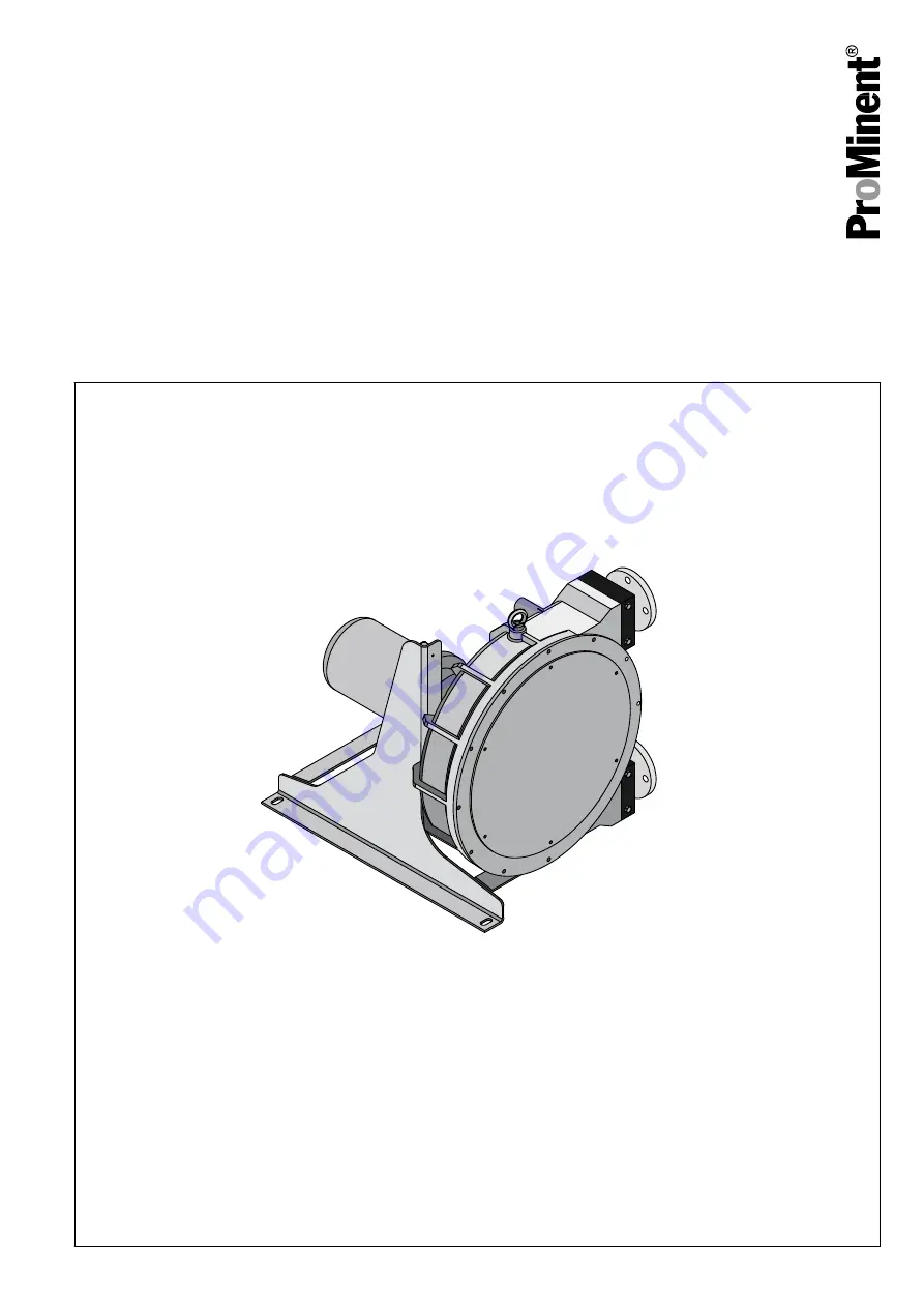
ProMinent DULCO flex DFCa Operating Instructions Manual Download Page 1

DULCO

®

flex DFCa

Peristaltic Pump

Operating instructions

A0374

EN

Original Operating Instructions (2006/42/EC)

Part no. 986227

BA DX 021 12/15 EN

Please carefully read these operating instructions before use. · Do not discard.

The operator shall be liable for any damage caused by installation or operating errors.

The latest version of the operating instructions are available on our homepage.

Summary of Contents for DULCO flex DFCa

Page 1: ...ions 2006 42 EC Part no 986227 BA DX 021 12 15 EN Please carefully read these operating instructions before use Do not discard The operator shall be liable for any damage caused by installation or ope...

Page 2: ...ludes detailed descriptions of the haz ardous situation see Chapter 1 1 Explanation of the safety information on page 4 The following symbols are used to highlight instructions links lists results and...

Page 3: ...3 Assembly 22 4 3 1 Ambient conditions 23 4 3 2 Alignment of the suction side 23 4 3 3 Alignment of the discharge side 24 4 3 4 Adjusting the roller pressure 24 4 3 5 Performance curves 27 5 Commissi...

Page 4: ...ure and source of the danger Consequence Fatal or very serious injuries Measure to be taken to avoid this danger Danger Denotes an immediate threatening danger If this is disregarded it will result in...

Page 5: ...should therefore only be con ducted by qualified personnel Unqualified personnel should be kept away from the hazard zone Training Definition Instructed personnel An instructed person is deemed to be...

Page 6: ...environment in which the are employed and know the relevant standards and regulations Electricians must comply with the provisions of the applicable statutory direc tives on accident prevention Custo...

Page 7: ...30 VAC A31 0 55 kW 11 39 rpm 286 1013 l h 20 70 Hz 4 bar A32 0 75 kW 18 63 rpm 468 1637 l h 20 70 Hz 2 bar Gear motor external frequency converter required 3 x 230 400 VAC A41 0 37 kW 2 28 rpm 52 727...

Page 8: ...base plate Leakage sensor 0 without leakage sensor L with leakage sensor M with leakage sensor and relay output Rotor 0 Rotor with 2 rollers Batch control 0 No batch control C With batch control Spec...

Page 9: ...10 kW 12 36 rpm 619 1857 l h 20 70 Hz 4 bar B32 1 50 kW 15 53 rpm 774 2735 l h 20 70 Hz 2 bar Gear motor external frequency converter required 3 x 230 400 VAC B41 1 10 kW 2 49 rpm 103 2528 l h 3 65 Hz...

Page 10: ...kage sensor 0 without leakage sensor L with leakage sensor M with leakage sensor and relay output Rotor 0 Rotor with 2 rollers Batch control 0 No batch control C With batch control Special version 0 S...

Page 11: ...th integrated frequency converter 1x 230 VAC C31 1 50 kW 8 29 rpm 706 2558 l h 20 70 Hz 4 bar C32 2 20 kW 17 60 rpm 1499 5292 l h 20 70 Hz 2 bar Gear motor external frequency converter required 3 x 23...

Page 12: ...less steel base plate Leakage sensor 0 without leakage sensor L with leakage sensor M with leakage sensor and relay output Rotor 0 Rotor with 2 rollers Batch control 0 No batch control Special version...

Page 13: ...Gear motor with integrated frequency converter 1x 400 VAC D31 3 0 kW 7 25 rpm 0 2 4 5 m3 h 4 bar D32 4 0 kW 7 59 rpm 3 2 11 2 m3 h 2 bar Gear motor 3 x 230 400 VAC external frequency converter requir...

Page 14: ...less steel base plate Leakage sensor 0 without leakage sensor L with leakage sensor M with leakage sensor and relay output Rotor 0 Rotor with 2 rollers Batch control 0 No batch control Special version...

Page 15: ...frequency converter 1x 400 VAC E31 5 5 kW 8 27 rpm 3 2 10 9 m3 h 20 60 Hz 4 bar E32 7 5 kW 13 38 rpm 5 2 15 3 m3 h 20 60 Hz 2 bar Gear motor 3 x 230 400 VAC external frequency converter required E41 5...

Page 16: ...plate Leakage sensor 0 without leakage sensor L with leakage sensor M with leakage sensor and relay output Rotor 0 Rotor with 2 rollers Batch control 0 No batch control Special version 0 Standard H H...

Page 17: ...nsequence Fatal or very serious injuries Measure Ensure that there can be no unauthor ised access to the unit WARNING Hazardous media contamination of persons and equipment Possible consequence Fatal...

Page 18: ...ential leakage of liquids must be accounted for If the hose rupture alarm optional is fitted then the pump can be stopped and or an elec trical valve can be actuated In addition you must avoid particl...

Page 19: ...ence Material damage right through to destruction of the unit The device is not suitable for outdoor operation Take suitable measures to protect the device from environmental influences such as UV ray...

Page 20: ...this pump type is often the optimal solution for abrasive shear sensitive and viscose media Typical areas of use include processes where only a low discharge pressure is required max 8 bar 3 1 Constr...

Page 21: ...3 2 Overview of the Device P_DX_0017_SW Fig 1 Diagram of functional principle 1 Housing 2 Rotor 3 Rollers 4 Hose Functional description 21...

Page 22: ...e hazard potential of a sub stance can be re evaluated at any time based on new findings The system operator is responsible for ensuring that these safety data sheets are available and that they are k...

Page 23: ...safety information see Chapter 2 1 General safety information on page 17 4 3 2 Alignment of the suction side The pump is to be positioned as near as possible to the liquid con tainer so that the sucti...

Page 24: ...empfohlen It is recommended to use a flexible transition between two fixed pipes and the hydraulic connection of the pump in order to avoid the transmission of vibrations 4 3 4 Adjusting the roller pr...

Page 25: ...can adapt the number of spacer plates to the actual operating conditions in accordance with the following table DFCa 030 Number of spacer plates of 0 5 mm thickness except Norprene rpm 0 19 20 39 40 5...

Page 26: ...14 14 Delivery state DFCa 050 Number of spacer plates of 1 0 mm thickness rpm 0 19 20 39 40 59 60 79 80 99 bar 0 5 1 1 1 0 0 2 0 2 1 1 1 1 4 0 2 2 2 2 2 6 0 3 3 3 3 8 0 4 3 Delivery state DFCa 060 Num...

Page 27: ...0 0 0 2 0 1 1 1 0 0 4 0 2 2 2 1 1 6 0 3 3 2 8 0 4 3 3 Delivery state 4 3 5 Performance curves NOTICE Maximum pressure under continuous operation The dotted line indicates the limit for maximum pres su...

Page 28: ...A0370 1 min l h 10 20 30 40 50 60 70 80 4400 3960 3520 3080 2640 2200 1760 1320 880 440 0 8 bar 4 bar 2 bar Fig 5 DFCa 040 A0371 Fig 6 DFCa 050 Transport storage assembly and Installation 28...

Page 29: ...A0372 Fig 7 DFCa 060 A0373 1 min m h 30 27 24 21 18 15 12 9 6 3 0 10 20 30 40 50 60 70 3 Fig 8 DFCa 070 Transport storage assembly and Installation 29...

Page 30: ...d n Check that the rollers are correctly fitted and fastened n Check that the hose and rollers are sufficiently lubricated n Check that the thermal overload protection not included in the delivery sco...

Page 31: ...tructed persons see Chapter 1 2 Users qualifications on page 5 The peristaltic pump is to be fully integrated into the customer s designated plant and is then controlled by this plant It is not pos si...

Page 32: ...oducing an associ ated hazard assessment for the workstations affected 7 1 Maintenance CAUTION Disconnect the pump from the mains Possible consequence Personal injury You may only carry out work on th...

Page 33: ...of the valves 7 3 Troubleshooting Problem Possible cause Solution Increased pump temperature Pump hose has no lubricant Lubricate pump hose Increased product temperature Reduce product temperature In...

Page 34: ...ing fluid and the lubricant High pump speed Reduce pump speed High conveying temperature Reduce product temperature High operating pressure Reduce operating pressure Pump cavitations Check the suction...

Page 35: ...or serious injuries In the event that damage to the pump hose contami nates the pump with the feed chemical decontaminate it with suitable agents refer to the material safety data sheet for the feed c...

Page 36: ...0 05 5 Roller holder 2 107 00 06 6 Spacer plate 107 00 07 7 Headless screw 2 107 00 08 8 Roller shaft 2 107 00 09 9 Roller 2 107 00 11 10 Metal cover 1 107 00 13 11 Front cover polycarbonate 1 107 00...

Page 37: ...Pump hose NORPRENE 1 107 00 54 1045073 16 Cap 1 110 00 23 17 Base plate left 1 100 01 24 Base plate left stainless steel 1 100 01 34 18 Base plate right 1 100 01 25 Base plate right stainless steel 1...

Page 38: ...6 00 06 6 Spacer plate 1 mm 106 00 07 Spacer plate 4 mm 106 00 49 7 Headless screw 2 106 00 08 8 Roller shaft 2 106 00 09 9 Roller 2 106 00 11 10 Metal cover 1 106 00 13 Metal cover vacuum design 106...

Page 39: ...93 Pump hose NBR A 1 106 00 21 1037196 Pump hose EPDM 1 106 00 22 1037194 Pump hose NORPRENE 1 106 00 50 1037198 16 Cap 1 110 00 23 17 Base plate left 1 106 00 24 Base plate left stainless steel 1 106...

Page 40: ...1 108 00 02 3 Rotor shaft 1 108 00 03 4 Rotor 1 108 01 04 5 Roller holder 2 108 01 05 6 Spacer plate 108 00 06 7 Headless screw 2 108 00 07 8 Roller shaft 2 108 00 08 9 Roller 2 108 01 09 10 Metal co...

Page 41: ...ORPRENE 1 108 00 45 1045084 16 Cap 1 104 01 23 17 Base plate left 1 108 00 26 Base plate left stainless steel 1 108 00 36 18 Base plate right 1 108 00 27 Base plate right stainless steel 1 108 00 37 1...

Page 42: ...s for DFCa 060 DFCa 060 see Fig 12 Item Description Quantity Reference Part number 1 Pump housing 1 110 01 01 2 Ball bearing housing 1 110 00 03 3 Rotor shaft 1 110 00 04 4 Rotor 1 110 01 05 5 Roller...

Page 43: ...I flange PVDF PTFE DN50 2 110 01 65 17 Pump hose NR 1 110 00 18 1037206 Pump hose NR A 1 110 00 19 1037210 Pump hose NBR 1 110 00 20 1037208 Pump hose NBR A 1 110 00 21 1037211 Pump hose EPDM 1 110 00...

Page 44: ...d bolts short 5 107 00 46 36 Stud bolts long 1 107 00 47 37 Knurled nut blank 5 102 00 26 38 Knurled nut 1 102 00 25 A0368 24 1 31 18 20 13 12 14 15 27 28 16 25 3 21 2 22 4 30 9 5 19 17 26 29 23 8 6 1...

Page 45: ...112 00 15 Connector DIN PVDF 2 112 00 16 Connector ANSI PVDF 2 112 00 17 Connector TRI CLAMP 2 112 00 43 15 Pump hose NR 1 112 00 18 1037213 Pump hose NR A 1 112 00 19 1037216 Pump hose NBR 1 112 00...

Page 46: ...112 00 29 29 Discharge screw 3 112 00 30 30 Additional spacer 1 112 00 31 31 Adapter rotor 2 112 01 32 34 O ring front cover 1 112 00 35 Lubricant Item Description Quantity Reference Part number 1 0 5...

Page 47: ...g Con nector 030 0 43 8 700 Rollers 28 7 0 62 1 1 4 040 0 81 8 1550 Rollers 35 8 8 89 1 1 2 050 1 46 8 2400 Rollers 40 10 0 140 DN 40 060 3 12 8 6000 Rollers 55 13 8 235 DN 50 070 8 05 8 12000 Rollers...

Page 48: ...5 mm M 1 1 4 Dependent on selected drive 8 2 Dimensions DFCa 040 A0376 Fig 15 Dimensions DFCa 040 A 135 mm B C D 70 mm E 613 mm F 345 mm G 552 mm H 385 mm I 170 mm J 130 mm K 330 mm L 95 mm M 1 1 2 De...

Page 49: ...8 3 Dimensions DFCa 050 A0377 Fig 16 Dimensions DFCa 050 A 151 mm B C D 79 mm E 645 mm F 415 mm G 633 mm H 453 mm I 200 mm J 159 mm K 412 mm L 115 mm Dependent on selected drive DFCa technical data 49...

Page 50: ...4 Dimensions DFCa 060 A0378 I I Fig 17 Dimensions DFCa 060 A 215 mm B C D 111 mm E 805 mm F 740 mm G 735 mm H 500 mm I 25 mm J 210 mm K 510 mm L 25 mm Dependent on selected drive DFCa technical data 5...

Page 51: ...5 Dimensions DFCa 070 A0379 Fig 18 Dimensions DFCa 070 A 215 mm B C D 250 mm E 1124 mm F 1065 mm G 1100 mm H 790 mm I 40 mm J 240 mm K 784 mm L 40 mm Dependent on selected drive DFCa technical data 5...

Page 52: ...o the product not approved by us will invalidate this declaration Extract from the EC Declaration of Conformity Designation of the product Peristaltic pump DULCOflex Product type DFAa DFBa DFCa DFDa S...

Page 53: ...Emergency stop switch 17 F Functional principle 21 G General non discriminatory approach 2 L Links to elements or sections of these instruc tions or other applicable documents 2 Live parts 17 M More s...

Page 54: ...54...

Page 55: ...55...

Page 56: ...986227 3 en_GB 2015 ProMinent GmbH Im Schuhmachergewann 5 11 69123 Heidelberg Telephone 49 6221 842 0 Fax 49 6221 842 419 Email info prominent com Internet www prominent com...

Reviews: