background image


Montageanleitung / 

Installation manual


MBN GmbH 

 Balthasar-Schaller-Str. 3 

 86316 Friedberg 

 Germany 

www.proled.com 

4. 

Testing Functions


1.  Automatic Funktions 


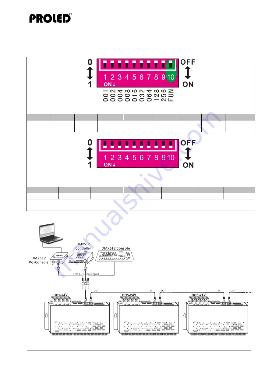
As diagram, FUN=ON: test function; 1-9DIP switch=OFF: BLACK 

DIP 1 

DIP 2 

DIP 3 

DIP 4 

DIP 5 

DIP 6 

DIP 7 

DIP 8 

DIP 9 

RED 

GREEN 

BLUE 

YELLOW  PURPURE 

CYAN 

WHITE 

SCAN 

Color 

gradual 


DIP8/DIP9 at “ON” is changing mode. 1-7 is to realize 8 speed levels. 7 is the fastest levels while dip 
switch 1-7=OFF: the speed is 0. 

DIP 1 

DIP 2 

DIP 3 

DIP 4 

DIP 5 

DIP 6 

DIP 7 

Speed 1 

Speed 2 

Speed 3 

Speed 4 

Speed 5 

Speed 6 

Speed 7 

As diagram, when several dip switches are on, subjected to the highest switch value, when all the 
dip switches=ON, it's the color gradual in the test mode, 7 speed level 
 

5.  Conjuction Diagramm 


The PROLED DMX PWM DIMMER 24-CHANNEL 
can be worked with any brand of DMX console. 
This connection diagram is an example of the 
DMX PC console, DMX controller, the DMX 
manual console and the DMX decoder. 
 
PROLED DMX PWM DIMMER 24-CHANNEL is 
equipped with two types DMX terminal for the 
user’s selection. This connection diagram is the 
example of the XRL-3 terminal, and user can also 
use green terminal.


Summary of Contents for DMX PWM DIMMING 24-CHANNEL

Page 1: ...verschiedene Übergangseffekte Ausgestattet mit DMX Standard XRL 3 und grünen Interface Buchsen ist er einfach zu bedienen PROLED DMX PWM DIMMER 24 KANAL kann einfarbige zweifarbige und RGB LED Lichter steuern 1 Technische Daten PROLED DMX PWM DIMMER 4 KANAL Signal Eingang DMX 512 Eingangs spannung DC 5 V DC 24 V Max Laststrom 3A Ch x 24 CH Max 72 A Max Leistungsausgang 360 W 864 W 1728 W 5 V 12 V ...

Page 2: ...16 032 064 128 256 ANMERKUNG DMX512 Startadresse ergibt sich aus den Einstellungen der DIP Schalter 1 9 die nach unten in die ON Position gesetzt sind DIP Schalter nach Oben in OFF Position bedeutet Wert 0 Beispiel Startadresse auf Wert 37 einstellen Schieben Sie den ersten dritten und sechsten DIP Schalter nach unten auf Wert 1 und den Rest auf 0 wie in Bild 2 Die Summe der Schalter 1 9 ist 1 4 3...

Page 3: ...IP 1 DIP 2 DIP 3 DIP 4 DIP 5 DIP 6 DIP 7 Geschw 1 Geschw 2 Geschw 3 Geschw 4 Geschw 5 Geschw 6 Geschw 7 Wie im Bild wenn verschiedene DIP Schalter an sind gilt die schnellste Geschwindigkeit Wenn alle DIP Schalter ON ist Farbwechsel im Test Mode sowie Geschwindigkeit 7 eingestellt 5 Anschluß Diagramm Der PROLED DMX PWM DIMMER 24 KANAL kann mit jeder DMX Steuerung zusammenarbeiten Dieses Anschlußdi...

Page 4: ... Verbindungen und Polaritäten richtig eingehalten sind um Beschädigungen an der LED zu verhindern 7 Falls ein Fehler auftritt schicken Sie bitte das Produkt an ihren Lieferanten zurück Bitte selber keine Fehlerbehebung vornehmen 8 Gewährleistungsbestimmungen 1 Wir bieten eine lebenslange technische Unterstützung für das Produkt an Wir gewähren eine 2 jährige Gewährleistung ab Kaufdatum Die Gewährl...

Page 5: ...r channel Realize 0 100 brightness and various changing effect Equipped with DMX standard XRL 3 and green terminal interface it s easy to operate PROLED DMX PWM DIMMER 24 CHANNEL can handle single color two color and RGB LED light 1 Product Parameter PROLED DMX PWM DIMMING 4 CHANNEL Signal Input DMX 512 Input Voltage DC 5 V DC 24 V Max current load 3A Ch x 24 CH Max 72 A Max output power 360 W 864...

Page 6: ...7 8 9 VALUE 001 002 004 008 016 032 064 128 256 REMARK DMX512 initial address is the total amount of the Dip switch 1 9 down dip switch to ON position User can get its place value Up dip switch to OFF position Its place value is 0 Example Set initial address to 37 Set the 1st 3rd 6th bit of the DIP switch downward to 1 the rest to 0 like figure 2 the summation from 1 to 9 is 1 4 32 so the DMX512 i...

Page 7: ...IP 3 DIP 4 DIP 5 DIP 6 DIP 7 Speed 1 Speed 2 Speed 3 Speed 4 Speed 5 Speed 6 Speed 7 As diagram when several dip switches are on subjected to the highest switch value when all the dip switches ON it s the color gradual in the test mode 7 speed level 5 Conjuction Diagramm The PROLED DMX PWM DIMMER 24 CHANNEL can be worked with any brand of DMX console This connection diagram is an example of the DM...

Page 8: ...re 6 Ensure all wire connections and polarities are correct before applying power to avoid any damages to the LED lights 7 If a fault occurs please return the product to your supplier Do not attempt to fix this product by yourself 8 Warrenty Agreement 1 We provide lifelong technical assistance with this product A 2 year warranty is given from the date of purchase The warranty is for free repair or...

Reviews: