


TDR-X
Operator’s Manual
26
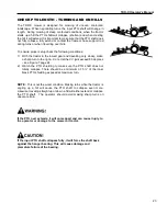
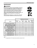
ADJUSTING THE MOWER FOR CUTTING
Ensure safety locks are properly engaged before attempting to
service mower. Make all adjustments with the tractor turned off,
key removed and parking brake set. Mower must be on level
ground before making adjustments.
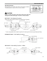
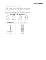
SETTING HEIGHT OF CUT
There are four height adjusters per mowing deck. Each adjuster (located in each corner of the deck) must be
adjusted to the same height to ensure a smooth even cut. In addition, each deck must be adjusted the same so
that a level cut is obtained across the whole cutting width of the mower. Mower cutting height adjustment is made
by turning a 5/8
” nut on top of an acme threaded rod which makes up the height adjuster. A pointer on the side
channel indicates the height against the scale. There are an infinite number of adjustments available from
3/8” to
3 3/8
”. Moving the adjuster up and down moves a side channel that mounts the front and rear rollers. Before
attempting to make height adjustments, the locking bolts on the side channels must be loosened. When the desired
adjustment is made, be sure to tighten the locking bolts to maintain the adjusted height. The height scales at the
back of the deck are set so that the back actually cuts slightly higher, this will provide a better cut, prolong the life
of the blades, and reduce horsepower requirement. This will also make the side channel look uneven, but this is
correct.
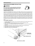
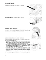
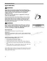
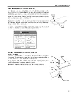
TDR-X HEIGHT ADJUSTER
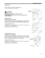
1. On flat level ground, place the decks on the ground and fully extend the deck cylinders until they are in the
center of the float slot.
2. Shut of the tractor and engage the parking brake. Work on one side of a single deck at a time
3. Using a
15/16” wrench, loosen both side channel lock bolts, do not remove
4.
Using a 15/16” wrench adjust Height Adjustment Nut to decided height of cut according to the adjacent scale
and indicator.
5. Repeat for the other adjustor on the same side channel
– setting it to the same height indication.
6. Securely tighten the two side channels lock bots to retain the cut height
7. Repeat steps 3 to 6 for the other side of the same deck.
8. Repeat above procedure for the remaining decks
Height Adjustment Nut
Height Scale
and Indicator
Side Channel Lock Bolt
Summary of Contents for TDR-X
Page 2: ......
Page 48: ...TDR X Operator s Manual 46 ...
Page 54: ...TDR X Parts Manual 2 1 DECK ASSEMBLY 1 1 Blade Spindle Assembly ...
Page 55: ...TDR X Parts Manual 3 1 2 Deck Assembly ...
Page 56: ...TDR X Parts Manual 4 1 3 Deck Side Channel Assembly ...
Page 57: ...TDR X Parts Manual 5 1 4 Gearbox Assembly ...
Page 58: ...TDR X Parts Manual 6 2 FRAME ASSEMBLY 2 1 Frame Assembly ...
Page 59: ...TDR X Parts Manual 7 2 2 Hitch Assembly ...
Page 60: ...TDR X Parts Manual 8 2 3 Right Wing Assembly ...
Page 61: ...TDR X Parts Manual 9 2 4 Left Wing Assembly ...
Page 62: ...TDR X Parts Manual 10 2 5 Rear Lift Assembly ...
Page 63: ...TDR X Parts Manual 11 2 6 Lock Release Assembly ...
Page 64: ...TDR X Parts Manual 12 2 7 Wheel Assembly ...
Page 65: ...TDR X Parts Manual 13 3 HYDRAULICS ...
Page 66: ...TDR X Parts Manual 14 4 DRIVELINE 4 1 Driveline Layout ...
Page 67: ...TDR X Parts Manual 15 4 2 Input PTO Shaft ...
Page 68: ...TDR X Parts Manual 16 4 3 Intermediate PTO Shaft ...
Page 69: ...TDR X Parts Manual 17 4 4 Wing Deck PTO Shaft ...
Page 70: ...TDR X Parts Manual 18 4 5 Rear Deck PTO Shaft ...
Page 71: ...TDR X Parts Manual 19 4 6 4 Way Gearbox ...


