background image

18

HOW TO USE A WEIGHT LOSS WORKOUT

1. Begin pedaling to turn on the console.

See step 1 on page 16.

2. Select a weight loss workout.

To select one of the four weight loss workouts,
press the Enter/Exit button repeatedly until the
name of a WEIGHT LOSS workout appears in the
upper display.

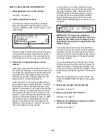
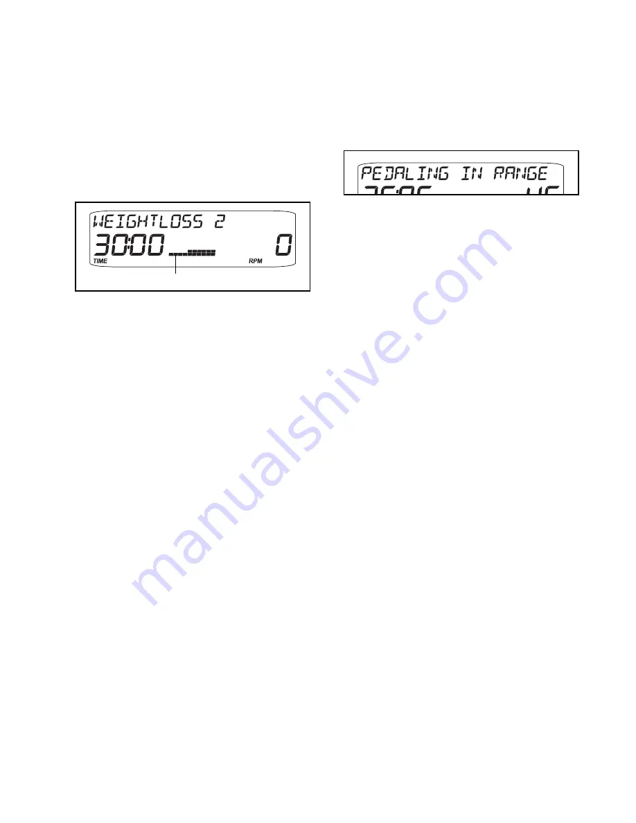
When you select a weight loss workout, the name
of the workout and the workout time will appear in
the displays and a profile of the resistance levels
of the workout will scroll across the center display.

3. Press Start or begin pedaling to start the 

workout.

Each weight loss workout is divided into 25, 30, or
45 one-minute segments. One resistance level and
one target rpm (revolutions per minute) setting are
programmed for each segment. Note: The same
resistance level and/or target rpm setting may be
programmed for consecutive segments.

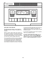
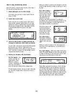
During the workout, the workout profile will show
your progress (see the drawing above). The flash-
ing segment of the profile represents the current
segment of the workout. The height of the flashing
segment indicates the resistance level for the cur-
rent segment. At the end of each segment of the
workout, a series of tones will sound and the next
segment of the profile will begin to flash. If a differ-
ent resistance level is programmed for the next
segment, the resistance level will appear in the
display for a few seconds to alert you. The resis-
tance of the pedals will then change.

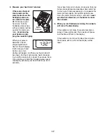
As you exercise, you will be prompted to keep
your pedaling pace near the target rpm setting for
the current segment. When the words PEDAL
FASTER appear in the upper display, increase
your pace. When the words PEDAL SLOWER
appear, decrease your pace. When the words
PEDALING IN RANGE appear, maintain your cur-
rent pace.

IMPORTANT: The target rpm settings are
intended only to provide motivation. Your actu-
al pace may be slower than the target rpm set-
tings. Make sure to pedal at a pace that is com-
fortable for you. 

If the resistance level for the current segment is
too high or too low, you can manually override the
setting by pressing the Quick Resistance buttons.
However, when the current segment ends, the ped-
als will automatically adjust to the resistance level
for the next segment.

If you stop pedaling for several seconds, a series
of tones will sound and the workout will pause. To
restart the workout, simply resume pedaling. The
workout will continue until the last segment of the
profile flashes and the last segment of the workout
ends. 

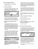
When the last segment of the workout ends, the
words PROGRAM DONE will appear in the upper
display.

4. Follow your progress with the displays.

See step 4 on page 16.

5. Measure your heart rate if desired.

See step 5 on page 17.

6. When you are finished exercising, the console

will turn off automatically.

See step 6 on page 17.

Profile

Summary of Contents for PFEL05807

Page 1: ...om new products prizes fitness tips and much more USER S MANUAL QUESTIONS As a manufacturer we are commit ted to providing complete customer satisfaction If you have questions or if parts are damaged...

Page 2: ...ORDERING REPLACEMENT PARTS Back Cover LIMITED WARRANTY Back Cover 2 WARNING DECAL PLACEMENT The warning decal shown here has been applied in the location shown If the decal is missing or illegible cal...

Page 3: ...s enough clearance around your elliptical exerciser to mount dismount and use it 5 Inspect and properly tighten all parts regu larly Replace any worn parts immediately 6 Keep children under age 12 and...

Page 4: ...over of this manual To help us assist you note the product model number and serial number before con tacting us The model number and the location of the serial number decal are shown on the front cove...

Page 5: ...the PART LIST near the end of this manual The number following the parentheses is the quantity needed for assembly IMPORTANT Some small parts may have been preassembled If a part is not in the hardwar...

Page 6: ...e Base 1 as shown and then insert the Base into the Frame Attach the Base with two M10 x 62mm Patch Bolts 97 two M10 Spacers 76 two M10 x 48mm Patch Screws 78 and two M10 Split Washers 72 Then careful...

Page 7: ...le two M10 x 25mm x 1 5mm Washers 83 and two M10 x 15mm Patch Screws 82 Repeat this step for the Left Roller Leg not shown and the Left Pedal Leg not shown 21 16 34 3 24 82 Grease 83 83 82 4 Identify...

Page 8: ...f white grease which is marked with a For Wheels sticker to the Roller 22 on the Right Roller Leg 21 spread the grease evenly around the Roller Slide the Right Roller Leg 21 onto the axle on the right...

Page 9: ...em Avoid pinching the Wire Harness 48 between the Upright and the Frame 8 9 Apply a generous amount of grease to the Pivot Axle 65 and insert it into the Frame 2 Orient the two Frame Covers 17 as show...

Page 10: ...his step for the Left Handlebar not shown 11 19 18 79 84 9 10 Identify the Right Handlebar 9 which is marked with an R sticker Insert the Right Handlebar into one of the Handlebar Legs 11 as shown Att...

Page 11: ...etighten the two console screws Then reattach the battery cover with the two battery screws The Console 5 can also be operated with an optional power supply instead of batteries To purchase a power su...

Page 12: ...e Right Pedal Leg 16 as shown and slide it onto the Pedal Leg Axle 32 Attach the Right Pedal Leg to the right Handlebar Leg 11 with two M10 x 15mm Patch Screws 82 two Axle Caps 31 and two M10 x 25mm x...

Page 13: ...the handlebars and step onto the pedal that is in the lower position Then step onto the other pedal Push the pedals until they begin to move with a continuous motion Note The crank arm covers can turn...

Page 14: ...more vertical path pivot the two selectors to the high position to adjust the elliptical exerciser so that the pedals move in a more horizontal path pivot the selectors to the low position IMPORTANT...

Page 15: ...and lose unwanted pounds The console guides you through an effective weight loss workout by prompting you to vary your pace and by automatically changing the resistance of the pedals The console also...

Page 16: ...or see step 5 on page 17 When you select a workout the left display will also show the approximate number of calories you have burned The center display When you select the manual mode this dis play w...

Page 17: ...st 15 seconds Note If you continue to hold the handgrip pulse sensor the display will show your heart rate for up to 30 seconds If your heart rate is not shown make sure that your hands are positioned...

Page 18: ...istance level will appear in the display for a few seconds to alert you The resis tance of the pedals will then change As you exercise you will be prompted to keep your pedaling pace near the target r...

Page 19: ...m fortable for you If the resistance level for the current segment is too high or too low you can manually override the setting by pressing the Quick Resistance buttons However when the current segmen...

Page 20: ...see the drawing below and locate the Reed Switch 50 Loosen but do not remove the indicated M4 x 16mm Self tapping Screw 79 Slide the Reed Switch slightly toward or away from a Magnet 55 on the flywhe...

Page 21: ...ur goal is to strengthen your cardiovascular system you must perform aerobic exercise which is activity that requires large amounts of oxygen for prolonged periods of time For aerobic exercise adjust...

Page 22: ...les Stretch With one leg in front of the other reach forward and place your hands against a wall Keep your back leg straight and your back foot flat on the floor Bend your front leg lean forward and m...

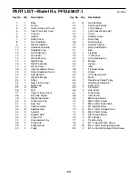
Page 23: ...del No PFEL05807 1 R0108A 89 71 96 84 81 80 18 19 41 79 93 41 8 10 11 87 88 88 14 13 33 33 93 37 28 93 33 33 41 41 42 82 85 7 12 22 24 34 35 41 82 82 83 83 93 30 54 60 82 83 31 32 31 82 41 82 79 86 79...

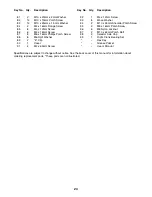
Page 24: ...1 Pulley Spacer 40 1 Pulley 41 12 Axle Bushing 42 2 Pedal Leg Endcap 43 1 Crank Sleeve 44 1 Left Crank Bearing Set 45 1 Crank 46 2 Selector Cover 47 4 Snap Ring 48 1 Wire Harness 49 2 Selector Spacer...

Page 25: ...Screw 92 1 M4 x 12mm Screw 93 8 Wave Washer 94 2 M10 x 35mm Shoulder Patch Screw 95 3 M8 x 16mm Patch Screw 96 6 M8 Nylon Locknut 97 2 M10 x 62mm Patch Bolt 98 2 Selector Axle Cap 99 1 Right Crank Bea...

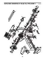
Page 26: ...5 95 95 17 77 77 86 86 86 36 75 38 44 45 47 43 2 99 47 57 39 36 38 75 70 70 3 66 74 74 40 47 52 96 96 94 58 20 47 53 61 73 50 59 79 62 56 4 4 63 20 85 85 69 25 25 97 78 72 76 92 27 73 73 73 94 55 55 9...

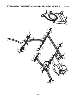
Page 27: ...80 81 93 15 31 31 30 32 33 33 54 60 7 21 22 24 35 41 41 41 41 42 82 83 83 82 82 82 82 82 82 88 83 83 88 87 9 10 29 84 71 96 41 93 93 86 79 79 79 79 16 85 93 34 98 49 46 89 83 83 83 EXPLODED DRAWING C...

Page 28: ...the customer will be responsible for a minimal trip charge This warranty does not extend to any product or damage to a product caused by or attributable to freight damage abuse misuse improper or abno...

Reviews: