MANUALE UTENTE –
USER’S MANUAL
Preamplificatore da incasso
Flush-Mounted Preamplifier
PREW
Page 1: ...MANUALE UTENTE USER S MANUAL Preamplificatore da incasso Flush Mounted Preamplifier PREW...
Page 2: ...2...
Page 3: ...3 INDICE I PRECAUZIONI D USO 4 II DESCRIZIONE 7 III PANNELLO FRONTALE 8 IV VISTA POSTERIORE 9 V INSTALLAZIONE 10 VI SCHEMA A BLOCCHI E CONNESSIONI 11 VII UTILIZZO 13 VIII CARATTERISTICHE TECNICHE 14...
Page 4: ...uso e manutenzione nel testo allegato Leggere il manuale RACCOMANDAZIONI Tutte le istruzioni di sicurezza e di funzionamento devono essere lette prima di mettere in funzione l apparecchio Conservare...
Page 5: ...lato sull apparecchio Se la spina in dotazione non combacia con la presa rivolgersi ad un elettricista per farsi installare una presa appropriata Messa a terra o polarizzazione Si devono prendere prec...
Page 6: ...namenti Non tentare mai di eseguire riparazioni diverse da quelle descritte nel presente manuale Contattare un centro di servizio autorizzato o del personale altamente qualificato nei seguenti casi Qu...
Page 7: ...na libreria o in altri luoghi a spazio ristretto PROEL S P A declina ogni responsabilit in caso di scorretta installazione dell unit Grazie per aver scelto un prodotto Proel e della fiducia riposta ne...
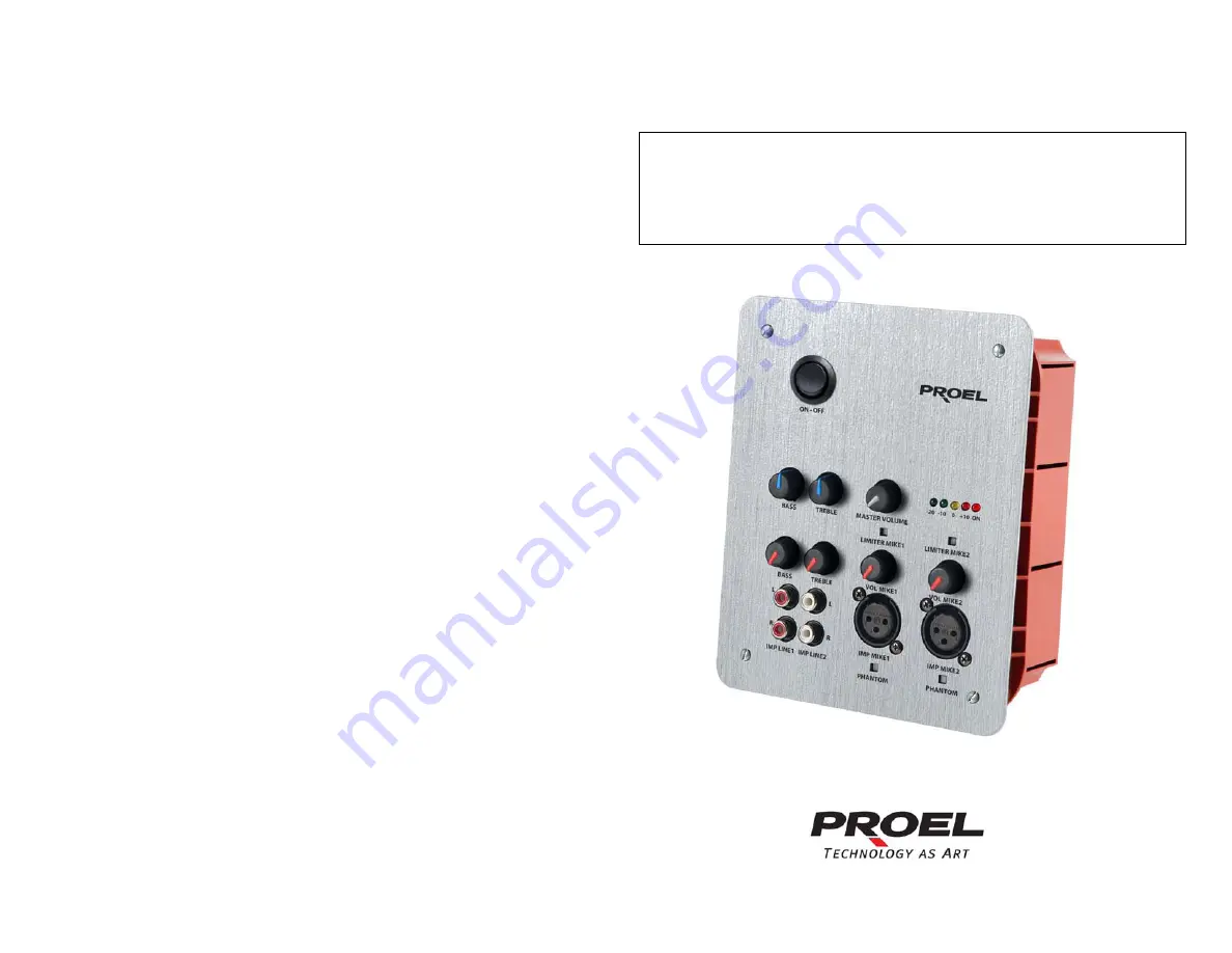
Page 8: ...Ingressi microfonici 5 Controllo guadagno ingresso microfonico 6 Ingressi di linea AUX 7 Controllo guadagno ingressi di linea AUX 8 Controlli di tono 9 Controllo livello di uscita master generale 10...
Page 9: ...13 Ingresso alimentazione 24 Vdc 14 Uscita segnale audio ad alto livello bilanciato 15 Jumper di selezione della sensibilit alta bassa ingresso MIC1 16 Jumper di selezione della sensibilit alta bassa...
Page 10: ...rne Nel caso d impiego di microfoni tradizionali sia dinamici che electrete impostare il jumper della sensibilit fig 2 rif 15 rif 16 sulla configurazione High Nel caso di impiego di microfoni sia dina...
Page 11: ...Gli ingressi MICRO 1 e MICRO 2 fig 1 rif 4 sono di tipo bilanciato utilizzabili per il collegamento sia di microfoni dinamici a bassa impedenza 250 600 sia di microfoni a condensatore con alimentazio...
Page 12: ...sbilanciato come da fig 4 Nota Per lunghe tratte con posa del cavo sottotraccia si consiglia vivamente la connessione bilanciata Il segnale d uscita viene regolato esclusivamente dal controllo di live...
Page 13: ...sonore dell ambiente 4 Ciascuno degli ingressi MICRO1 MICRO2 AUX1 ed AUX2 possiede un proprio controllo di volume indipendente che consente di regolare nella maniera ottimale il volume di riproduzion...
Page 14: ...150mV 10Kohms Frequency range 3dB 50 18KHz Tone Control BASS TREBLE Outputs Pre OUT Balanced 1 V 600ohm THD distortion 0 5 Pnom 1Kz S N Ratio 80 dB Mic Input Sensibility H 2 2mV 50 dBu L 7 7mV 40 dBu...
Page 15: ...15 INDEX I IMPORTANT SAFETY INSTRUCTIONS 16 II DESCRITION 19 III FRONT PANEL 20 IV REAR VIEW 21 V INSTALLATION 22 VI BLOCK DIAGRAM AND CONNECTIONS 23 VII USE 25 VIII TECHNICAL CHARACTERISTICS 26...
Page 16: ...ating and maintenance servicing instruction in the literature accompanying the appliance Please carefully read the owner s manual INSTRUCTIONS All safety and operating instructions should be read befo...
Page 17: ...to power source type specified in this owner s manual or on the unit If the supplied AC power cable plug is different from wall socket please contact an electrician to change the AC power plug Ground...
Page 18: ...n fire or electric shock Damages requiring services Don t attempt to do operations not described in this user s manual In the following cases please refer to an authorized maintenance center or skille...
Page 19: ...all room PROEL S P A is not responsible for any damage that occurs due to a wrong unit installation Thank you for choosing one of Proel products and for your confidence towards our brand synonymous of...
Page 20: ...status and Vu meter output 4 Microphone Input 5 Micophone Input Gain Control 6 LINE AUX inputs 7 LINE AUX gain control inputs 8 Tone control 9 Master output level control 10 Phantom power supply contr...
Page 21: ...wer supply input 13 24 Vdc power supply input 14 High level and balanced audio signal output 15 MIC1 input Sensibility jumper selection high low 16 MIC2 input jumper sensibility selection high low 17...
Page 22: ...propriate Unit power supply inputs In case of traditional microphone use Dynamic or Electret Set the Jumper sensibility fig 2 ref 15 ref 16 High configuration In case of Dynamic or Electret microphone...
Page 23: ...NNECTIONS fig 3 The input MICRO 1 and MICRO 2 fig1 ref 4 are balanced and can be used for both connections for dynamic microphones with low impedance 250 600 and for condenser microphone with Phantom...
Page 24: ...gths and for cables layout balanced connexions are keenly recommended The output signal is exclusively controlled by MASTER level potentiometer PREW unit can be directly connected to the main installa...
Page 25: ...ent sound characteristics 4 The inputs MICRO1 MICRO2 AUX1 and AUX2 features proper independent volume control to allow optimal output volume control 5 To increase volume level rotate clockwise MASTER...
Page 26: ...600ohms with 12V Phantom 2 x AUX 150mV 10Kohms Frequency range 3dB 50 18KHz Tone Control Bass Treble Outputs Pre OUT Balanced 1 V 600ohm THD distortion 0 5 Pnom 1Kz S N Ratio 80 dB Mic Input Sensibili...
Page 27: ...27...
Page 28: ...28 PROEL S p A World Headquarters Factory Via alla Ruenia 37 43 64027 Sant Omero Te Italy Tel 39 0861 81241 Fax 39 0861 887862 E mail info proelgroup com installation proelgroup com...