F
frequency converters
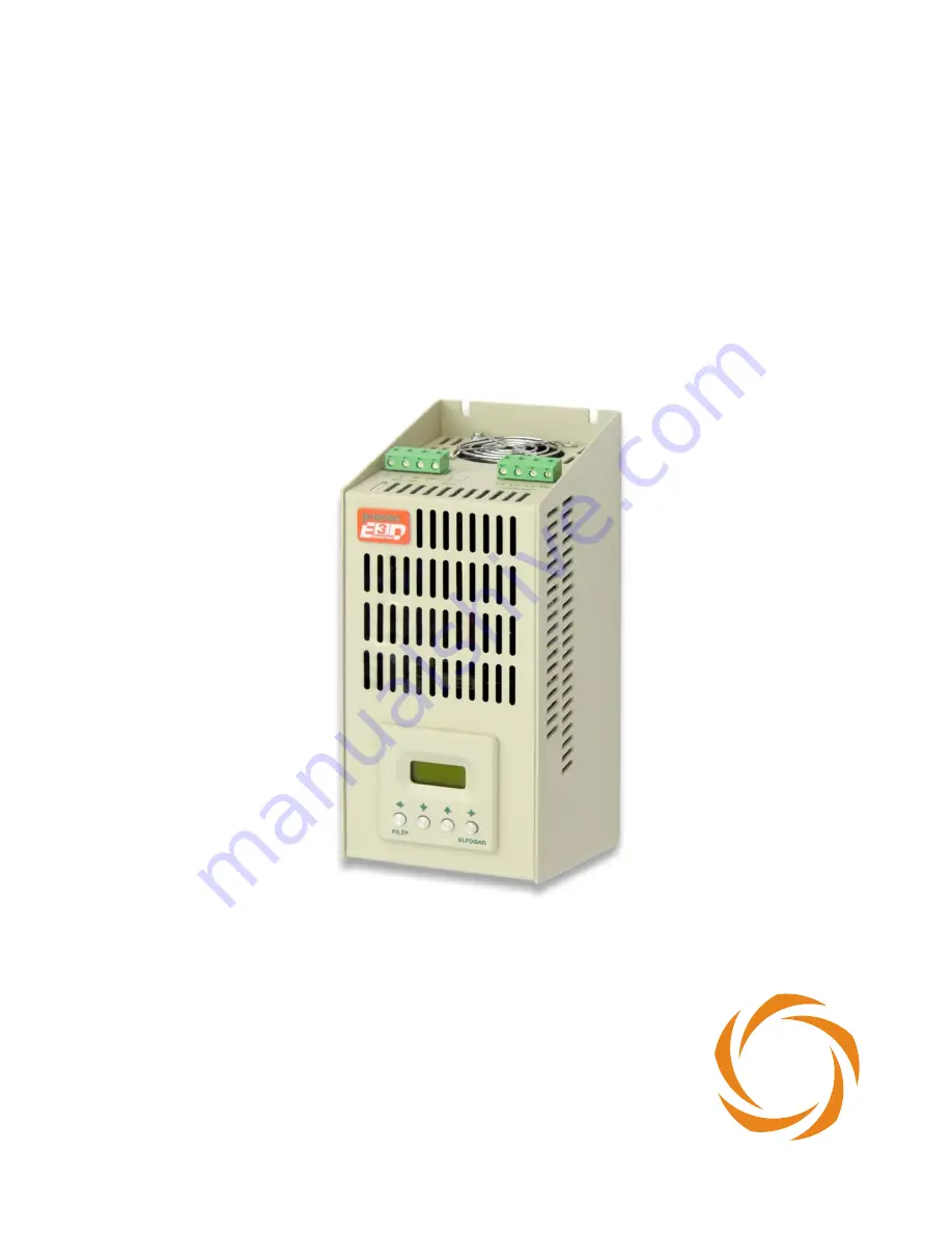
instruction manual 0,55
–
4
kW
from software version V164
P
Since
1984
Page 1: ...F frequency converters instruction manual 0 55 4 kW from software version V164 P Since 1984...
Page 2: ......
Page 3: ...FREQUENCY CONVERTER FOR THE FIRST TIME 9 ASSIGNMENT AND CONNECTION OF THE E3D TERMINAL BLOCK 10 OPERATING THE CONVERTER 11 Controlling terminal 11 Functions of the push buttons 11 PROGRAMMING 12 Prog...
Page 4: ...This symbol is used for those instructions whose negligence could cause personal injury damage in the equipment and property damage i Important information APPLICATION The E3D series frequency convert...
Page 5: ...netic compatibility EMC the listed products are not considered as products which can be operated alone The electromagnetic compatibility can only be evaluated after the product was incorporated in the...
Page 6: ...the environment and the device becomes totally dry The appliance must not be put into operation in humid environment The circuitries of the frequency converter must not be modified or changed In switc...
Page 7: ...earthing conductor and avoid earth loops Earthing conductors common with machines of higher power e g welding machine machine tool must not be used For wiring the control unit use shielded cable Use s...
Page 8: ...choke coil is not enough because of the excessive capacitive load In this case a sine filter has to be used Regarding the output choke coil or the sine filter please ask the manufacturer s opinion Co...
Page 9: ...th brake check up the value and the placing of the brake resistor page 16 Selection of the brake resistors at dynamic braking Switch the line power to the device At devices without controlling termina...
Page 10: ...GND reference point of the inputs SA4 Analogue input 2 feedback signal 0 10 V 4 20 mA 0 20 mA SD1 Digital input 1 factory setting start switch SD2 Digital input 2 factory setting reversing switch SD3...
Page 11: ...he frequency converter only Functions of the push buttons Escape Change between display mode and programming mode Parameter setting mode shift the cursor to the left Repeated push exit parameter setti...
Page 12: ...l Term motor pot Motor pot Analogue In 1 16 RRefS Regulation reference source Selecting the source of the regulation reference signal Analogue In 1 Terminal Term motor pot Motor pot Analogue In 1 17 P...
Page 13: ...f more than one input is programmed for reversing switch then activating each further input results in reversing the direction of the rotation Example with two digital inputs programmed for reversing...
Page 14: ...pper frequency corner point of the U vs f characteristics 0 1 400 0 50 0 Hz 64 UMot Nominal voltage Nominal line voltage of the motor This is the voltage the motor obtains at f fmot Menu item 63 This...
Page 15: ...istor too high Increase the run down time in menu item 32 StopM Over Cur The current developed through the motor exceeded the maximum value Decrease the load of the motor DC High The DC voltage in the...
Page 16: ...of 660 V DC The appliance must be installed and wired very carefully because of heat developing and for proper electric shock protection For wiring use cables with heat resisting coating MAINTENANCE A...
Page 17: ...Three phase 3 x 380 440 V AC input E3D 0 55 0 55 1 7 2 3 1 5 100 220 107 70 x 210 4 x M4 E3D 0 75 0 75 2 6 4 1 5 100 220 107 70 x 210 4 x M4 E3D 1 1 1 1 3 2 5 2 100 240 144 70 x 230 4 x M4 E3D 1 5 1 5...
Page 18: ...USB RS 485 interface RS 485 485 interface optical light cable type USB RS 485 interface optical light cable type CAN bus 1 CAN bus 2 Reception of incr rotation speed encoder 1 Reception of incr rotat...
Page 19: ......
Page 20: ...ocon hu Internet www procon hu Edition April 2018 I II III IV V VIII IX X XI XII XIII XIV XV XVI XVII XVIII XIX XX XXI XXIII XXII B a r o s s u V c i t T m r u Nyitra u Tin di u Per nyi Zsigm ond u Ki...