


8
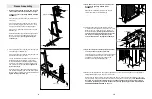
9.
Remove the lower pre-assembled Pulley (35) from
the Press Frame (12). Set the Pulley, the 3/8” x 8 1/2”
Bolt (59), and the 3/8” Nylon Locknut (50) aside.
Wrap the High Cable (73) around the upper pre-
assembled Pulley (35) in the direction shown.
Feed the bolt on the High Cable (73) through the indi-
cated slot in the Main Upright (3).
Lay the High Cable (73) over a 4” Pulley (35). Attach
the Pulley inside the Main Upright (3) with a 3/8” x 2
1/2” Bolt (54), two 3/8” Flat Washers (55), two Pulley
Bushings (42), and a 3/8” Nylon Jamnut (63).
10. Feed the bolt on the High Cable (73) back through
the indicated slot in the Main Upright (3) in the direc-
tion shown.
Wrap the High Cable (73) around the 4” Pulley (35)
that was removed from the Press Frame (12) in step
9. The Cable must wrap around the Pulley in the
direction shown. Attach the Pulley to the Press Frame
with the 3/8” x 8 1/2” Bolt (59) and the 3/8” Nylon
Locknut (50).
Feed the bolt on the High Cable (73) back through
the slot in the Main Upright (3) in the direction shown.
9
10
12
9
Bolt
Slot
35
73
55
54
42
55
3
42
63
Bolt
Slot
35
35
73
55
50
50
54
73
42
55
59
59
3
3
12
35
35
12
Slot
Bolt
Lower Pre-
assembled
Pulley (35)
42
63
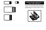
19. Important: Follow both cables from end to end
and make sure that they rest in the grooves of all
pulleys and that the cables and pulleys move
smoothly.
Unscrew the bolt at the end of the High Cable (73)
from the Weight Tube (36). Thread the 1/2” Plain Nut
(68) partway onto the bolt.
Slide the 5 7/8” Long Bushing (76) over the top of the
Weight Tube (36). Place the 1 1/2” Flat Washer (40)
on top of the Weight Tube and the Long Bushing.
Tighten the bolt at the end of the High Cable (73) into
the Weight Tube (36). Note: The bolt at the end of
the High Cable is the primary means for tighten-
ing both Cables. Thread the bolt into the Weight
Tube until both Cables are tight and rest firmly in
the grooves of all pulleys.
When both Cables (73, 72 [not shown]) are tight,
tighten the 1/2” Plain Nut (68) onto the 1 1/2” Flat
Washer (40).
Insert the Weight Pin (39) into one of the holes
between the Weights (26).
19
Bolt
76
36
26
39
40
68
73
45
50
1
18. Feed the end of the Low Cable (72) through the indi-
cated slot in the Main Upright (3).
Wrap the Low Cable (72) over a 4” Pulley (35). Attach
the Pulley inside the Main Upright (3) with a 3/8” x 2
1/2” Bolt (54), two 3/8” Flat Washers (55), two Pulley
Bushings (42), and a 3/8” Nylon Jamnut (63).
Note: It may be necessary for a second person to
pull the lower end of the High Cable (not shown)
to lift the top weight off the weight stack while
you perform this step.
18
Slot
63
42
17. Slide a Cable Trap (44) onto a 3/8” x 4” Bolt (65).
Wrap the Low Cable (72) around a 4” Pulley (35).
Attach the Pulley to the indicated hole in the Main
Upright (3) with the 3/8” x 4” Bolt (65), the Cable Trap
(44), a Pulley Bushing (42), a 3/8” Flat Washer (55),
and a 3/8” Nylon Jamnut (63). Make sure the Cable
Trap is oriented as shown, so it will hold the
Cable in place.
17
42
35
63
55
35
42
72
3
55
54
65
44
3
72
55
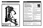
8.
Remove the upper 3/8” x 3” Bolt (45) attaching the
Top Frame (1) to the Main Upright (3).
Feed the bolt on the High Cable (73) down through
the indicated slot in the Main Upright (3) as shown.
Note: Follow the procedure described in step 7
for attaching all pulleys. Lay the High Cable (73)
over a 4” Pulley (35) in the direction shown. Attach
the Pulley inside the Main Upright (3) with a 3/8” x 2
1/2” Bolt (54), two 3/8” Flat Washers (55), two Pulley
Bushings (42), and a 3/8” Nylon Jamnut (63).
Make sure that the High Cable (73) is in the
groove of the 4” Pulley (35). Re-insert the 3/8” x 3”
Bolt (45) and secure it with a 3/8” Nylon Locknut (50).