
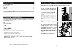


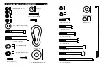


ADJUSTING THE POSITION OF THE BACKREST
To adjust the position of the Backrest (41), unscrew the
indicated Adjustment Knob (9) until it is loose. Pull out the
Adjustment Knob as far as it will go and slide the
Backrest Frame (15, not visible) to the desired position.
Release the Adjustment Knob and let it snap into one of
the adjustment holes in the Backrest Frame. Then,
retighten the Adjustment Knob.
ADJUSTING THE POSITION OF THE PRESS FRAME
HANDLES
To adjust each Handle (20) on the Press Frame (46),
unscrew the Adjustment Knob (9) until it is loose. Pull out
the Adjustment Knob as far as it will go and slide the
Handle to the desired position. Release the Adjustment
Knob until it snaps into one of the adjustment holes in the
Handle. Then, retighten the Adjustment Knob.
Note: Both Handles (20) should always be in the
same position.
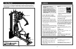
USING THE LEG LEVER LOCK
Some exercises, such as sit-ups, can be performed more
comfortably with the Leg Lever (29) locked.
To lock the Leg Lever (29), turn the Leg Lever Lock (11)
until it engages the Pad Tube (28) on the Leg Lever.
3
18
WARNING:
Before beginning this or any exercise program, consult your physician. This
is especially important for persons over the age of 35 or persons with pre-existing health problems.
Read all instructions before using. ICON assumes no responsibility for personal injury or property
damage sustained by or through the use of this product.
Important Precautions
1. It is the responsibility of the owner to ensure
that all users of the training system are ade-
quately informed of all precautions.
2. Read all instructions in this manual and in
the accompanying literature before using the
training system.
3. The training system is intended for home use
only. Do not use the training system in a
commercial, rental, or institutional setting.
4. If you feel pain or dizziness at any time while
exercising, stop immediately and begin cool-
ing down.
5. Use the training system only on a level sur-
face. Cover the floor beneath the training
system to protect the floor or carpet.
6. Inspect and tighten all parts often. Replace
any worn parts immediately.
7. The training system is designed to be used
by only one person at a time.
8. Keep children under the age of 12 and pets
away from the training system at all times.
9. Keep hands and feet away from moving parts.
10. Always wear athletic shoes for foot protec-
tion while exercising.
11. Always stand on the foot plate when per-
forming an exercise that could cause the
training system to tip.
12. Make sure the cables remain on the pulleys
at all times. If the cables bind while you are
exercising, stop immediately and make sure
the cables are on all of the pulleys.
13. Never release the press arm, leg lever, lat
bar, row bar, ab strap, or ankle strap while
weights are raised. The weights will fall with
great force.
14. Always disconnect the lat bar or row bar
from the training system when performing an
exercise that does not require them.
WARNING:
To reduce the risk of serious injury, read the following important
precautions before using the training system.
9
20
20
9
41
Adjustment
Holes
46
11
28
29
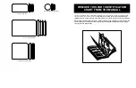
The warning decals shown at the right have
been pre-attached to the training system in the
locations shown on page 4. Note that decal #1
has been placed in two locations. If a decal is
missing, or if it is not legible, please call our
Customer Service Department at 0345-089009
for a free replacement decal. Apply the new
decal to the training system in the appropriate
location.
• Keep clear of
this area.
Warning Decal #1
Warning Decal #2
Keep hands and
fingers clear of
this area.
Warning Decal #3
9