Pro-Form Stride Select 825 User Manual Download Page 13

81

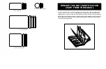
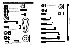
Note: “#” indicates a non-illustrated part. Specifications are subject to change without notice. 

1

1

Top Frame

2

1

3/8” x 1 1/2” Button Cap Screw 

3

1

Main Upright

4

1

Foot Plate

5

1

Stabiliser

6

1

Leg Lever Bumper

7

1

#10 x 1” Tap Screw

8

1

Base

9

4

Adjustment Knob

10

1

Ankle Strap

11

1

Leg Lever Lock

12

1

Press Frame

13

1

Seat

14

2

Plastic Sleeve

15

1

Backrest Frame

16

1

Top Weight

17

10

1/4” x 3/4” Bolt

18

6

1 1/8” x 1/2” Flange Bushing

19

2

Weight Bumper

20

2

Handle

21

2

5/16” Nylon Locknut

22

1

1/2” x 3 1/2” Bolt

23

2

Weight Guide

24

3

2” x 3” Inner Cap

25

2

1/4” Nylon Locknut

26

14

Weight 

27

1

Pivot Rod

28

2

Pad Tube

29

1

Leg Lever

30

4

Foam Pad

31

2

Pulley Plate

32

4

#8 x 3/4” Screw

33

8

2” Square Inner Cap

34

6

3/4” Round Inner Cap

35

15

4” Pulley

36

1

Weight Tube

37

1

Seat Upright

38

4

Threaded Clip

39

1

Weight Pin

40

1

1 1/2” Flat Washer

41

1

Backrest

42

21

5/8” x 1/2” Pulley Bushing, 

43

2

1” x 2” Inner Cap

44

3

Cable Trap

45

4

3/8” x 3” Bolt

46

1

Press Arm

47

2

1/2” x 1/8” Flange Bushing 

48

1

1/2” Nylon Jamnut

49

4

1/4” x 1 1/2” Screw

50

13

3/8” Nylon Locknut

51

4

1/4” Nylon Jamnut

52

2

3/8” x 3 3/4” Carriage Bolt

53

2

Large Washer

54

10

3/8” x 2 1/2” Bolt

55

22

3/8” Flat Washer

56

1

Shroud

57

1

3/8” x 5 1/2” Bolt

58

6

Grip

59

2

3/8” x 8 1/2” Bolt

60

4

3/8” x 1 3/4” Bolt

61

1

Lat Bar

62

1

3/8” x 2” Bolt

63

15

3/8” Nylon Jamnut

64

1

Weight Support

65

2

3/8” x 4” Bolt

66

1

Weight Cover

67

1

Chain 16”

68

1

1/2” Plain Nut

69

3

Cable Clip

70

1

Row Bar

71

2

1/4” Flat Washer

72

1

Low Cable

73

1

High Cable 

74

2

Leg Foam Pad

75

1

Ab Strap

76

1

5 7/8” Long Bushing

77

28

Weight Insert

78

3

5/16” x 3” Bolt

79

1

5/16” Nylon Jamnut

80

3

5/16” Flat Washer

#

1

User’s Manual

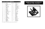
REMOVE THIS PART LIST/EXPLODED

DRAWING FROM THE MANUAL

Part List—Model No. PFEMSY75001                        

R0301A

Key No.

Qty.

Description

Key No.

Qty.

Description

Summary of Contents for Stride Select 825

Page 1: ...he space above QUESTIONS As a manufacturer we are committed to providing complete customer satisfaction If you have questions or if there are missing parts we will guarantee complete satisfaction thro...

Page 2: ...he other adjustment holes in the Pulley Plates To do this remove the 3 8 x 1 3 4 Bolt 60 the Cable Trap 44 and the 3 8 Nylon Jamnut 63 Move the Pulley and re attach it with the Bolt Cable Trap and Loc...

Page 3: ...for home use only Do not use the training system in a commercial rental or institutional setting 4 If you feel pain or dizziness at any time while exercising stop immediately and begin cool ing down...

Page 4: ...at the end of the Weight Pin is touching the Weights The setting of the weight stack can be changed from 10 pounds to 150 pounds in incre ments of 10 pounds Note Due to the cables and pul leys the am...

Page 5: ...BLY REQUIRES TWO PERSONS For your convenience and safety assemble the training system with the help of another person SET ASIDE ENOUGH TIME Due to the many features of the training system the assembly...

Page 6: ...through the bracket and the Main Upright 3 from the side Hand tighten two 5 16 Nylon Locknuts 21 onto the Bolts Do not tighten the Nylon Locknuts yet 65 50 55 78 33 29 33 8 Front Leg 3 21 29 Make sur...

Page 7: ...iser 5 Attach the indicated Weight Guide 23 to the Stabiliser 5 with a 3 8 x 2 1 2 Bolt 54 two 3 8 Flat Washers 55 two Pulley Bushings 42 and a 3 8 Nylon Jamnut 63 5 23 19 55 5 23 19 Hole 63 55 42 42...

Page 8: ...hed Weight Tube 36 onto the Weight Guides 23 The Weight Tube will slide into the hole in the centre of the Weights 26 Place the Top Frame 1 over the Weight Guides 23 so the Weight Guides fit into the...

Page 9: ...he end of the High Cable is the primary means for tighten ing both Cables Thread the bolt into the Weight Tube until both Cables are tight and rest firmly in the grooves of all pulleys When both Cable...

Page 10: ...h Cable 73 around a 4 Pulley 35 Attach the Pulley inside the Main Upright 3 with a 3 8 x 2 1 2 Bolt 54 two 3 8 Flat Washers 55 two Pulley Bushings 42 and a 3 8 Nylon Jamnut 63 11 55 42 63 3 35 42 55 5...

Page 11: ...s below each part refers to the key number of the part Important Some parts may have been pre assembled for shipping purposes If you cannot find a part in the parts bags check to see if it has been pr...

Page 12: ...2 Bolzen 62 3 8 x 2 1 2 Bolzen 54 3 8 x 3 Bolzen 45 3 8 x 4 Bolzen 65 3 8 flachen Unterlegscheibe 55 Rollenbuchse 42 5 16 flachen Unterlegscheibe 80 5 16 Nylon Kontermutter 79 8 x 3 4 Schraube 32 3 8...

Page 13: ...aded Clip 39 1 Weight Pin 40 1 1 1 2 Flat Washer 41 1 Backrest 42 21 5 8 x 1 2 Pulley Bushing 43 2 1 x 2 Inner Cap 44 3 Cable Trap 45 4 3 8 x 3 Bolt 46 1 Press Arm 47 2 1 2 x 1 8 Flange Bushing 48 1 1...

Page 14: ...68 40 76 26 39 49 2 16 51 64 66 51 63 55 42 54 55 42 35 42 42 35 42 42 63 60 31 35 31 35 44 44 35 42 42 63 63 54 60 50 1 55 55 42 35 42 42 35 42 55 35 42 42 35 14 73 42 42 55 14 43 43 28 30 34 34 30 5...

Reviews: