


11
10
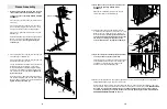
12. Disassemble the Pulley Plates (31). Note that on one
end the Pulley Plates have several adjustment holes.
These holes must be closest to the floor.
Wrap the High Cable (73) under a 4” Pulley (35).
Attach the Pulley to the upper ends of the Pulley
Plates (31) with a 3/8” x 1 3/4” Bolt (60), a Cable Trap
(44), and a 3/8” Nylon Jamnut (63). Make sure that
the Cable is in the groove of the Pulley and that
the Cable Trap is oriented as shown, so it will
hold the Cable in place.
Set the other 4” Pulley, 3/8” x 1 3/4” Bolt, Cable Trap,
and 3/8” Nylon Jamnut aside (these parts are not
shown).
12
73
60
31
44
35
31
63
Adjustment
Holes
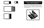
13. Feed the bolt on the High Cable (73) up through slot
A in the Top Frame (1) as shown.
Lay the High Cable (73) over a 4” Pulley (35). Attach
the Pulley inside slot A with a 3/8” x 2 1/2” Bolt (54),
two 3/8” Flat Washers (55), two Pulley Bushings (42),
and a 3/8” Nylon Jamnut (63).
Lay the High Cable (73) over another 4” Pulley (35)
and feed the bolt on the High Cable down through
slot B in the Top Frame (1) as shown. Attach the
Pulley inside slot B with a 3/8” x 2 1/2” Bolt (54), two
3/8” Flat Washers (55), two Pulley Bushings (42), and
a 3/8” Nylon Jamnut (63).
See the inset drawing. Thread the bolt on the High
Cable (73) two turns into the top of the Weight Tube
(36).
13
1
42
55
35
35
42
55
54
63
42
63
73
42
55
54
55
Bolt
Slot B
Slot A
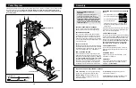
11. Wrap the High Cable (73) around a 4” Pulley (35).
Attach the Pulley inside the Main Upright (3) with a
3/8” x 2 1/2” Bolt (54), two 3/8” Flat Washers (55), two
Pulley Bushings (42), and a 3/8” Nylon Jamnut (63).
11
55
42
63
3
35
42
55
54
73
15. Route the Low Cable (72) through the indicated slot
in the Main Upright (3) and the Base (8).
Wrap the Low Cable (72) around a 4” Pulley (35) in
the direction shown. Attach the Pulley to the welded
bracket on the Main Upright (3) with a 3/8” x 2” Bolt
(62) and a 3/8” Nylon Locknut (50).
15
50
3
72
8
35
62
Slot
73
36
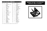
14. Identify the Low Cable (72), which is the only remain-
ing cable. Note that it has a large ball on one end and
a small ball on the other.
Route the small ball on the Low Cable (72) through
the indicated slots in the Leg Lever (29) and the front
leg on the Base (8).
Attach a 4” Pulley (35) inside the slot in the Leg Lever
(29) with a 3/8” x 2 1/2” Bolt (54), two 3/8” Flat
Washers (55), two Pulley Bushings (42), and a 3/8”
Nylon Jamnut (63).
Attach a 4” Pulley (35) inside the slot in the front leg
on the Base (8) with a 3/8” x 2 1/2” Bolt (54), two 3/8”
Flat Washers (55), two Pulley Bushings (42), and a
3/8” Nylon Jamnut (63).
14
55
42
72
42
55
29
35
8
63
Slots
Larger Ball
42
55
42
55
54
35
16. Wrap the Low Cable (72) over a 4” Pulley (35). Attach
the Pulley and the Cable Trap (44) to the lowest
adjustment hole in the Pulley Plates (31) with a 3/8” x
1 3/4” Bolt (60) and a 3/8” Nylon Jamnut (63). Make
sure that the Cable is in the groove of the Pulley
and that the Cable Trap is oriented as shown, so
it will hold the Cable in place.
16
31
Adjustment
Holes
63
60
35
44
72