


Hardware Modifications
156
Fan Kit Installation and Removing
Overview
Before installing or removing a fan kit, shut down Windows® in an orderly fashion
and remove all power from the device.
Fan Kit Installation
NOTE:
Only qualified personnel can change the fan kit.
NOTE:
Modifying products to install an HDD into a Slide-in Disk slot when it was not
installed from factory, requires to change the unit firmware settings for proper
behavior of the fan (that are required when running with HDD into a Slide-in Disk) -
Please contact Pro-face support if you want to proceed such modification.
The table below describes how to install a fan kit:
DANGER
HAZARD OF ELECTRIC SHOCK, EXPLOSION OR ARC FLASH
Remove all power from the device before removing any covers or elements of
the system, and prior to installing or removing any accessories, hardware, or
cables.
Unplug the power cable from both the Industrial Personal Computer and the
power supply.
Always use a properly rated voltage sensing device to confirm power is off.
Replace and secure all covers or elements of the system before applying power
to the unit.
Use only the specified voltage when operating the Industrial Personal
Computer. The AC unit is designed to use 100...240 Vac input. The DC unit is
designed to use 24 Vdc. Always check whether your device is AC or DC
powered before applying power.
Failure to follow these instructions will result in death or serious injury.
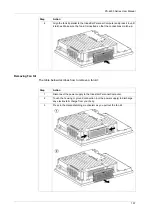
Step
Action
1
Disconnect the power supply to the Industrial Personal Computer.
2
Touch the housing or ground connection (not the power supply) to discharge
any electrostatic charge from your body.
3
Remove the cover.
Summary of Contents for PS-4600 Series
Page 1: ......
Page 12: ...About the Book 12...
Page 14: ...General Overview 14...
Page 26: ...Important Information 26...
Page 56: ...Implementation 56...
Page 72: ...Industrial Personal Computer Connections 72...
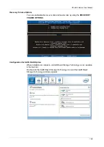
Page 78: ...Configuration of the BIOS 78 Platform Information The figure shows the Main submenu...
Page 118: ...Hardware Modifications 118 The figure shows the dimensions of the UPS battery unit...
Page 170: ...Hardware Modifications 170...
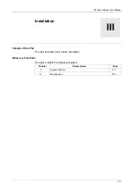
Page 172: ...Installation 172...
Page 192: ...192...
Page 196: ...After sales service 196...


