E4-1
GP2000 Series VM Unit User Manual
Chapter 4 : SETUP
This section describes how to adjust the images received from the VIDEO IN cable.
First, switch your GP/GLC/ABS unit to OFFLINE mode. For GP/GLC2000 Series
OFFLINE mode details , refer to
"GP2400/2500/2600 Series User Manual"
"GLC2400/2500/2600 Series User Manual"
For GP/ABS3000 Series OFFLINE mode details, refer to
"Maintenance/Troubleshooting"
You can also adjust your VM Unit via the [GP System Setup] area in the GP-PRO/
PBIII for Windows (for GP/GLC2000 Series Users) or [Video Module Settings] of
the System Settings Window in the GP-Pro EX (for GP3000 Series Users) / Pro EX
for BA(for ABS3000 Series Users).
4.1.1
SET UP VIDEO OPERATION
Here, you can enter the parameters that control the display of your video signal.
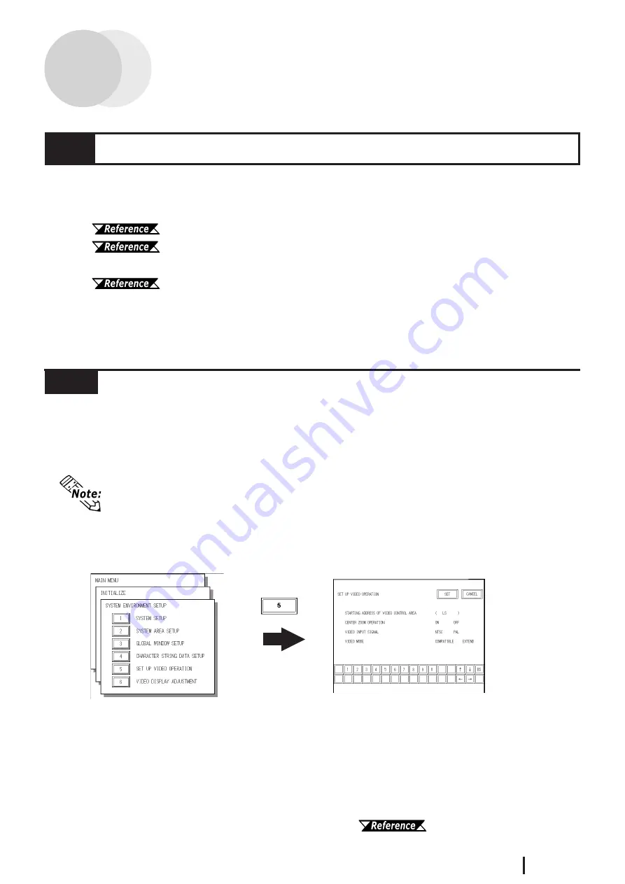
To display the setup screen, select the "INITIALIZE", "SYSTEM ENVIRONMENT
SETUP" and "VIDEO DISPLAY ADJUSTMENT" screens. (The SETUP VIDEO
OPERATION screen will appear only when the VM Unit is installed.)
STARTING ADDRESS OF VIDEO CONTROL AREA
In the GP/GLC LS area, you can designate "LS0020" through "LS2010" as the start-
ing address of the video control area. After the starting address is specified, in "
COM-
PATIBLE
" mode 22 continuous words (in "
EXTEND
" mode 43 continuous words),
beginning from the starting address are assigned as the video control area. Designat-
ing "LS0000" as the starting address disables the VM Unit feature.
For the details of the video control area, refer to
"GP-PRO/PB III for
Windows Tag Reference Manual" (included with the screen editor software)
.
4.1
Video Window Adjustment
• Here describes the operation when using GP/GLC2000 Series. When using
GP/ABS3000 Series units, to display the setup screen, select the OFFLINE
mode, “Main Unit Settings”, “Video Module Setiings”, and “Video System
Environment Settings” screens. For details, refer to “Maintenance/Trouble-
shooting”.


