


Installation and Wiring
66
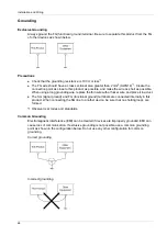
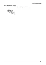
Grounding
Exclusive Grounding
Always ground the FG (functional ground) terminal. Be sure to separate this product from the FG
of other devices as shown below.
Precautions
Check that the grounding resistance is 100
or less
*1
.
The FG wire should have a cross sectional area greater than 2 mm
2
(AWG14)
*1
. Create the
connection point as close to this product as possible, and make the wire as short as possible.
When using a long grounding wire, replace the thin wire with a thicker wire, and place it in a duct.
The SG (signal ground) and FG (functional ground) terminals are connected internally in this
product. When connecting the SG line to another device, be sure that no shorting loops are
formed.
*1 Observe local codes and standards.
Common Grounding
Electromagnetic interference (EMI) can be created if devices are improperly grounded. EMI can
cause loss of communication. If exclusive grounding is not possible, use a common grounding
point as shown in the configuration below. Do not use any other configuration for common
grounding.
Correct grounding
Incorrect grounding
Summary of Contents for FP5000 Series
Page 1: ...FP5000 Series User Manual FP5000 MM01 EN PDF_02...
Page 6: ...6...
Page 10: ...10...
Page 22: ...Overview 22 KC Markings...
Page 26: ...Device Connectivity 26...
Page 30: ...Parts Identification and Functions 30...
Page 48: ...Dimensions 48 FP 5600TPD External Dimensions 1 Front 2 Left 3 Bottom...
Page 50: ...Dimensions 50 FP 5700TPD External Dimensions 1 Front 2 Left 3 Bottom...
Page 52: ...Dimensions 52...
Page 72: ...Installation and Wiring 72...


