FP-3710K Series User Manual
6-2
6.1
Operation Mode Setup
6.1.1
Preset Settings and Adjustments for Dip Switch and Slide Switch
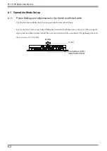
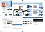
The Dip Switches and Slide Switch are located in the bottom of the FP unit.
Loosen the screws of the cover with a Phillips head screwdriver and then remove the cover. After setting the
dip switches and slide switches, reinstall the cover and screws with the screwdriver. The tightening torque for
those screws is 0.5 to 0.6 N•m.
Bottom
Dip Switches (SW1)
Slide Switch (SW2)
Cover
Summary of Contents for FP-3710K Series
Page 1: ...3 6HULHV 8VHU 0DQXDO...
Page 17: ...16...
Page 18: ...1 1 1 System Design 1 FP 3710K Series 2 Cables for connecting with computer...
Page 21: ...FP 3710K Series User Manual 1 4...
Page 22: ...2 1 2 Optional Equipment 1 Optional Equipment...
Page 28: ...3 1 3 Part Names and Functions 1 FP 3710K Series...
Page 31: ...FP 3710K Series User Manual 3 4...
Page 57: ...FP 3710K Series User Manual 5 12...
Page 67: ...FP 3710K Series User Manual 6 10...
Page 71: ...FP 3710K Series User Manual 7 4...
Page 85: ...FP 3710K Series User Manual 8 14...
Page 86: ...9 1 9 Troubleshooting 1 Troubleshooting 2 Error Message...
Page 93: ...FP 3710K Series User Manual 9 8...
Page 103: ...FP 3710K Series User Manual 10 10...

