background image


11  - 

PRM125


i) The Gearbox operating Lever is provided with a positive neutral position, which greatly assists the setting up of the 
remote control unit. 
 

ii) CAUTION: CARE SHOULD BE TAKEN TO ENSURE THAT THE FLEXIBLE CABLE IS CAPABLE 
AND CAN MOVE THE FEARBOX LEVER FREELY TO THE FULL EXTENT OF ITS  TRAVEL BOTH 
FORWARD AND BACKWARD AND THAT ITS NEUTRAL POSITION IS CORRECT FOR THIS TO TAKE 
PLACE.


The control equipment should in all cases be connected in accordance with the manufacturer’s recommendations. 
 

6. OPERATION 


6.1 First time usage 


CAUTION: 

Before starting the Engine fill the Gearbox to the correct level with a suitable oil (refer 

to recommended list, section 4.3). 


Ensure the Gearbox is in neutral. Start and run the Engine for a short time so that the oil circulates through the 
Gearbox. Stop the Engine and allow the oil to settle for two minutes, re-check the level and top up to the marked oil 
level. 

NOTE: 

The Dipstick should be pushed down when checking the oil level. 


6.2 Drive selection 

 
The PRM125D has been designed to operate with proprietary single Lever control systems which decreases the Engine 
speed to idle before opposite Gear selection can be made. It is most important that when changing direction a short 
pause is taken in neutral at engine idle before selecting Gear. (see section 5.7) 
 

6.3 Trailing (free wheeling) the Propeller 

 
The Output Shaft can be rotated in neutral continually with the Engine shut down which makes the PRM125D 
particularly suited for use in auxiliary sailboats, sailing yachts etc. Never put the Lever in the position corresponding to 
the direction of the Vessel. 
 

7. ROUTINE MAINTENANCE 


7.1 Initial maintenance (after 25 hours running) 

Drain all oil from the Gearbox, the Drain Plug is located on the side of the Transmission, below the Selector Lever. A 
25.4mm (1.0’’) across flats spanner is required. Refit Drain Plug. 
 
Refill with oil as stated in 4.3. 
 

7.2 Daily checks 

Check the Gearbox oil level on Dipstick. 
Visually inspect for oil leaks and general condition of the Gearbox. 
 

7.3 Six monthly check 

Check the remote control operating linkage is accurately adjusted to give maximum travel (stop to stop) in both 
directions. 
 

7.4 Annual check 

All above checks. 
Propeller Shaft alignment inspection. 
Change Gearbox oil and after 500 hours or annually which ever comes first. 


7.5 Cone Clutch adjustment 

The Cone Clutch is self- adjusting and therefore needs no adjustment. Should Gear selection become difficult it is 
advisable to check the installation and operaion of the Control Cable as discribed in 5.7. if this is correct then the Cone 
Clutch adjustment can be carried out as decribed in 9.7.6. if problems persist after the adjustment. It will be necessary 
to dissassemble the Gearbox to investigate the condition of the Cone Clutch.  
If the Cone Clutcvh shows signs of loss of coating, glazing and heat discoloration and the mating Gears shows signs of 
heavy groove indentations then the Cone Clutch and the Mating Gears must be replaced. If only the Gears are replaced 
then the adjustment of the Cone Clutch is not required. If the cone Clutch is replaced then adjustment needs to be 
carried out as described in 9.7.6. 


Summary of Contents for PRM125D

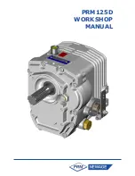
Page 1: ...PRM125D WORKSHOP MANUAL...

Page 2: ...and therefore reserves the right to change specifications without prior notification Whilst every effort is made to ensure complete accuracy of the information in this manual no liabilities for inaccu...

Page 3: ...d oils and oil filling 7 5 INSTALLATION 8 5 1 General 8 5 2 Checking the engine Flywheel Housing 8 5 3 Checking the Engine Flywheel 8 5 4 Mounting the Gearbox to the Engine 10 5 5 Alignment to Propell...

Page 4: ...8 Gearcase 14 9 7 Re assembly of gearbox 14 9 7 1 Input Shaft 14 9 7 2 Output Shaft see 9 7 5 for shimming procedure 14 9 7 3 Idler Shaft 15 9 7 4 Selector housing assembly 15 9 7 5 Shimming 15 9 7 6...

Page 5: ...e Ltd direct quoting the serial number CLAIMS UNDER WARRANTY Claims for replacement of parts under warranty must always be submitted with the Gearbox serial number to the distributor who supplied the...

Page 6: ...erial number and should always be quoted when ordering spare parts the lower line is the Gearbox specification in the example given this translates as follows 125 D 2 First 2 digits Gearbox Model 125...

Page 7: ...sification without labouring 1 GENERAL DATA 1 1Specifications Gear ratios ahead 2 04 1 2 50 1 3 06 1 Gear ratio astern 2 44 1 common POWER RATING AHEAD RATIO PLEASURE LIGHT COMMERCIAL BHP kW BHP kW 2...

Page 8: ...facilitate servicing 3 2 Gear train The helical Gear train is manufactured from high grade Steel with all Gears being case hardened for long life All Shafts are supported on Taper Roller Bearings whic...

Page 9: ...elp find solutions to potential torsional problems but it is the ultimate responsibility of the person assembling the drive and driven equipment to ensure that they are torsionally compatible 5 2 Chec...

Page 10: ...9 PRM125 BASIC INSTALLATION DETAILS PRM125D Figure 4 Intallation Details...

Page 11: ...Shaft and stern tube to be maintained Whether a solid of flexible coupling is used it is extremely important that the following points are carefully checked i the Coupling should be a tight press fit...

Page 12: ...use in auxiliary sailboats sailing yachts etc Never put the Lever in the position corresponding to the direction of the Vessel 7 ROUTINE MAINTENANCE 7 1 Initial maintenance after 25 hours running Dra...

Page 13: ...tallation Remove examine and replace if necessary Check the alignment of the Propeller Shaft Coupling if necessary rectify by adjusting the Shims under the Engine mounts or the Engine mounts themselve...

Page 14: ...parts in solvent to remove dirt grease and oil Be careful to remove solvent from items before re fitting 9 4 Inspection 9 4 1 Gearcase Inspect for cracks Check sealing surfaces for any scratches damag...

Page 15: ...Gear 24 and remove the Bearing 28 cone Check condition of the O Ring 49 on the Idler Shaft 2 9 6 6 Selector By hand remove Selector Shoe 9 and the Spring 8 Remove the Lever 13 Pass the Selector Contro...

Page 16: ...haft lengths over Bearings to achieve shim requirement Dimension Y A 6 Fit shims as required to within zero to 0 05mm pre load Place the Shims into the appropriate bore of the Front Cover 29 so that t...

Page 17: ...of the Selector Shoe 9 and the Dog Point Grub Screw 17 at max cone eccentricity CAUTION This condition can only be maintained with the clutch at the top dead centre If this is not achieved the gear s...

Page 18: ...SHER 2 23 0563201 NEEDLE BEARING 2 24 MT8406 IDLER GEAR 1 25 001 0270 BEARING 4 26 0672801 THRUST WASHER 2 27 0320470 INTERNAL SPRING RING 1 28 0540252 BEARING 2 29 MT8621 FRONT CASE 1 30 MT8095 BINX...

Page 19: ...18 PRM125 13 Exploded view and Cross section Figure 5 Exploded view and cross section...

Page 20: ...19 PRM125...

Page 21: ...20 PRM125...

Page 22: ...21 PRM125...

Page 23: ...ODUCTS MT8684 KIT 2 1 MT8684 MT8687 MT8688 FORWARD GEAR REVERSE GEAR CONE CLUTCH PRM120 PRM125 MT8685 KIT 2 5 1 MT8685 MT8687 MT8688 FORWARD GEAR REVERSE GEAR CONE CLUTCH PRM120 PRM125 MT8686 KIT 3 1...

Reviews: