PRM NEWAGE PRM 60 Workshop Manual Download Page 21


19   -  

PRM 60


Fit drain and oil level plugs (26) with bonded washer (31) to the sides of the gearcase (2). Fit oil filling plug (48) with 
bonded washer (54). Fit dipstick (28) and breather (30) with bonded washer (52). Finally adjust the gear selector lever 
(44) into the required position. 


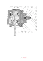
9.7.6 Cone Clutch Selection 

 
With the selector lever (44) in neutral position manually rotate the output coupling (23). The eccentricity of the cone 
clutch (11) groove causes an axial shift on the selector shoe (22). The variable distance between the end of the selector 
shoe (22) and the output shaft (14) vertical centre line upon rotation provides MAX & MIN axial movement of the 
selector shoe (22). With no further rotation of the output coupling (23), screw the dog point grub screw (50) until contact 
is made with the bottom of the selector shoe (22). Fit the nut (49) upto selector body (18), 

not 

allowing any rotation of 

the dog point grub screw (50). Unscrew the dog point grub screw (50) simultaneously with the nut (49) attached until a 
0.60mm gap is achieved between the nut (49) and the selector body (18). With no further movement of the dog point 
grub screw (50) tighten the nut (49) against the selector body (18) to 17 Nm (13lbft). This will give 0.60mm clearance 
between the bottom of the selector shoe (22) and the dog point grub screw (50) at max cone eccentricity. 


CAUTION:

 This condition can only be maintained with the clutch at the top dead centre. If this is not 

achieved the gear selection will be affected, creating difficulty in gear engagement or disengagement. 


10. SPECIAL TOOLS 

 
Oil seal to selector housing   


PR29418 

Oil seal to gearcase 


PR29281 

Oil seal to front cover 


PR29283 


10.1 Tool Kit 

 
Socket size 


13mm 


24mm 


30mm 

Drain Plug 


13mm A/F 


10.2 Tightening torques 


RECOMMENDED TIGHTENING TORQUES


Size 

Grade 

Type 

Nm 

M6


8.8 

Bolt


12 

M8 

8.8 

Nut 

24 

M8 

8.8 

Screw 

30 

M16 

8.8 

Binx Nut 

56 

M16 

8.8 

Special Nut 

170 

*


M25 

8.8 

Locknut 

135 

*NOTE: USE LOCTITE 243 ON THREADS AND STAKE NUT INTO KEYWAY. 


11. REPLACEMENT PARTS ORDERING 

When ordering replacement parts the following should be quoted: 
 

a) Gearbox model and serial number 
b) Description(s) and part number(s) of the component(s) required 
c) Quantity required 
d) Orders and enquiries for replacement parts must be made through PRM Newage distributor/dealer network 


NOTE:

 Enquiries relating to a technical or service nature can be made direct to: 


PRM NEWAGE LTD. 

BARLOW ROAD 

COVENTRY CV2 2LD 

ENGLAND 


TEL: +44 (0)24 7661 7141 


Summary of Contents for PRM 60

Page 1: ...PRM 60 WORKSHOP MANUAL...

Page 2: ......

Page 3: ...for inaccuracies or the consequences thereof can be accepted by the manufacturer or the distributor who supplied the manual This manual contains proprietary information of PRM Newage Limited It is int...

Page 4: ...ed oils and oil filling 7 5 INSTALLATION 8 5 1 General 8 5 2 Checking the Engine Flywheel Housing 8 5 3 Checking the Engine Flywheel 8 5 4 Mounting the Gearbox to the Engine 10 5 5 Alignment to Propel...

Page 5: ...of Gearbox 17 9 7 1 Input shaft 17 9 7 2 Output shaft see 9 7 5 for Shimming procedure 17 9 7 3 Idler Shaft 18 9 7 4 Selector Housing assembly 18 9 7 5 Shimming Output Bearings 18 9 7 6 Cone Clutch Se...

Page 6: ...e Ltd direct quoting the serial number CLAIMS UNDER WARRANTY Claims for replacement of parts under warranty must always be submitted with the gearbox serial number to the distributor who supplied the...

Page 7: ...serial number and should always be quoted when ordering spare parts the lower line is the gearbox specification in the example given this translates as follows 60 D 2 First 2 digits Gearbox Model 60...

Page 8: ...abouring 1 GENERAL DATA 1 1Specifications Gear ratios ahead 1 52 1 2 00 1 2 50 1 Gear ratio astern 2 05 1 common POWER RATING MODEL AHEAD RATIO PLEASURE LIGHT COMMERCIAL BHP kW BHP kW 60D1 5 1 52 1 0...

Page 9: ...itate servicing 3 2 Gear train The helical gear train is manufactured from high grade steel with all gears being case hardened for long life All shafts are supported on ball bearings which are amply p...

Page 10: ...elp find solutions to potential torsional problems but it is the ultimate responsibility of the person assembling the drive and driven equipment to ensure that they are torsionally compatible 5 2 Chec...

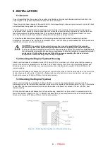
Page 11: ...9 PRM 60 BASIC INSTALLATION DETAILS PRM 60 Figure 4 Intallation Details...

Page 12: ...housing and tighten fully See fastening torque chart 10 2 5 5 Alignment to Propeller Shaft CAUTION Alignment between the propeller shaft and the mating flange on the gearbox output shaft is extremely...

Page 13: ...d whilst the hull is afloat otherwise there is a danger of the hull distorting because of an insufficient support over its surface If the engine and transmission are fitted before the hull is in water...

Page 14: ...upper hole Make sure the lever forward position corresponds to the forward movement of the vessel The following points should be noted i The gearbox operating lever is provided with a positive neutral...

Page 15: ...when checking the oil level 6 2 Drive selection The PRM 60 has been designed to operate with proprietary single lever control systems which decreases the engine speed to idle before opposite gear sel...

Page 16: ...s first 7 5 Cone Clutch Adjustment The cone clutch is self adjusting and therefore needs no adjustment Should gear selection become difficult it is advisable to check the installation and operaion of...

Page 17: ...tallation Remove examine and replace if necessary Check the alignment of the propeller shaft coupling if necessary rectify by adjusting the shims under the engine mounts or the engine mounts themselve...

Page 18: ...parts in solvent to remove dirt grease and oil Be careful to remove solvent from items before re fitting 9 4 Inspection 9 4 1 Gearcase Inspect for cracks Check sealing surfaces for any scratches dama...

Page 19: ...ng 15 Remove the lever 44 Pass the selector control body 18 through the housing 19 and remove O ring 20 and oil seal 21 if replacing them 9 6 7 Front Cover If it is required to replace the front cover...

Page 20: ...ths Dimension Y 5 Subtract bore face lengths from shaft 14 lengths over bearings 33 to achieve shim requirement Dimension Y A 6 Fit shims as required to within zero to 0 025mm preload Place the shims...

Page 21: ...crew 50 tighten the nut 49 against the selector body 18 to 17 Nm 13lbft This will give 0 60mm clearance between the bottom of the selector shoe 22 and the dog point grub screw 50 at max cone eccentric...

Page 22: ...MT8103 SELECTOR SHOE 1 23 MT8670 OUTPUT COUPLING 1 24 0400286 OIL SEAL 1 25 MT8674 BINX NUT 1 26 0150125 BSP LEVEL PLUG 1 27 0210614 DOWEL PIN 2 28 0970147 3 8 BSP FILLER DIPSTICK 1 29 N A SERIAL PLAT...

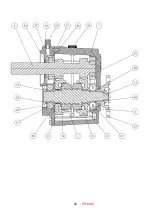
Page 23: ...21 PRM 60 13 Exploded view and Cross section Figure 5 Exploded view and cross section...

Page 24: ...22 PRM 60...

Page 25: ...23 PRM 60...

Page 26: ...24 PRM 60...

Page 27: ...ESCRIPTION PRODUCT MT8677 KIT 1 5 1 MT8677 MT8680 MT8688 FORWARD GEAR REVERSE GEAR CONE CLUTCH PRM 60 MT8678 KIT 2 1 MT8678 MT8680 MT8688 FORWARD GEAR REVERSE GEAR CONE CLUTCH PRM 60 MT8679 KIT 2 5 1...

Page 28: ...26 PRM 60 NOTES...

Page 29: ...n specifications are subject to change without notice Accordingly data given herein should be regarded as a general guide only and does not form part of any contract Any specific performance requireme...

Reviews: