


Chapter 5
General Operation Factors
35
Note:
Do not be concerned about either the DC level of this background noise or its
shape unless it is very high, i.e., > 1000 counts with 16-bit A/D. What you see is not
noise. It is a fully subtractable readout pattern. Refer to
,
page 38, for more information.
If you observe a sudden change in the baseline signal you may have excessive humidity
in the camera's CCD enclosure.
Immediately
turn off the controller.
Then, contact
Princeton Instruments Customer Support for further instructions. See page 146 for
contact information
.
Clean Cycles
As stated before, dark charge integrates on the array whenever the camera is on, whether or
not data acquisition is occurring. To minimize the dark charge and other noise in the pixel
wells when data acquisition is idle, the Clean Cycles function shifts accumulated charge in a
predefined number of rows to the shift register and then discards it.
Clean cycles start when you turn on the camera and a clean pattern is programmed into it. At
the end of a cycle, the camera checks to see if a Start Acquisition command has been
received. If it has been received, the user-defined number of cleans (typically 0) will be
then performed before the exposure starts. If a Start Acquisition has not been received, the
next clean cycle begins.
The number of rows that are shifted and discarded during a clean cycle are defined in the
application software (for example, on the WinView/WinSpec
Setup|Hardware|Cleans/
Skips
tab page). The most effective cleaning occurs when the number of rows equals the
number of rows on the CCD. However, you need to keep in mind that a clean cycle must be
completed before a Start Acquisition command will be implemented. The more rows in a
cycle, the greater the delay between the command receipt and the beginning of an exposure.
Because of this timing issue, the number of rows per clean cycle is usually much smaller than
the number of rows on the array.
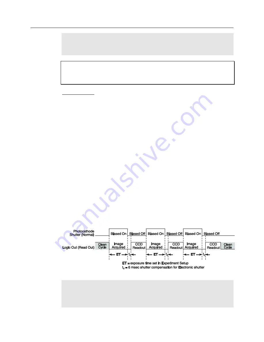
The timing diagram below is for an experiment set up to acquire three (3) images using
Internal trigger mode (selected on
SuperSYNCHRO Trigger In
tab page) and Gate Mode
(selected on
Experiment Setup Main
tab page). In this diagram, clean cycles occur before
the first exposure and after the last readout period. They do not need to occur between
exposures since each readout cleans the array before the next exposure starts.
Figure 7. Clean Cycles in Internal Trigger Mode of Operation
Note:
The start of the exposure is signaled by the
Read Out
output of the
LOGIC OUT
connector going low but will not occur until the current clean cycle and the additional
user-defined number of cleans (typically 0) have finished. "Number of Cleans" is defined
on the
Setup|Hardware|Cleans/Skips
tab page. If you enter a value other than "0", you
will further delay the start of the exposure by that number of clean cycles.
WARNING!
Summary of Contents for PI-MAX 3 System
Page 1: ...4411 0129 Version 1 A September 8 2010 4411 0069 ...
Page 32: ...32 PI MAX 3 System Manual Version 1 A This page intentionally left blank ...
Page 52: ...52 PI MAX 3 System Manual Version 1 A Figure 20 Safe Mode and Fast Mode Operation ...
Page 72: ...72 PI MAX 3 System Manual Version 1 A This page intentionally left blank ...
Page 90: ...90 PI MAX 3 System Manual Version 1 A This page intentionally left blank ...
Page 100: ...100 PI MAX 3 System Manual Version 1 A This page intentionally left blank ...
Page 110: ...110 PI MAX 3 System Manual Version 1 A Figure 68 Outline Drawing PI MAX3 with F mount Adapter ...
Page 114: ...114 PI MAX 3 System Manual Version 1 A This page intentionally left blank ...
Page 120: ...120 PI MAX 3 System Manual Version 1 A This page intentionally left blank ...
Page 140: ...140 PI MAX 3 System Manual Version 1 A This page intentionally left blank ...