Princeton Instruments NIRvana-LN User Manual Download Page 89

Chapter 10

Troubleshooting

89

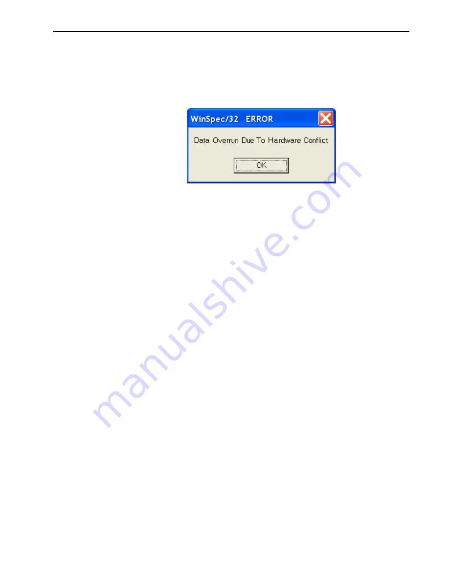
10.4 Data Overrun Due to Hardware Conflict Message Displayed

If this dialog appears when acquiring a test image, acquiring data, or running in focus mode, 
check the array size and then check the DMA buffer size. A large array (e.g., a 2048x2048 
array,) requires a larger DMA buffer larger setting than that for a smaller array (e.g., a 
512x512 array.)

Figure 10-4: Data Overrun Due to Hardware Conflict Dialog

Perform the following procedure to change the DMA buffer size:

1.

Note the array size listed on the 

Setup|Hardware|Controller/CCD

 tab or on the 

Acquisition|Experiment Setup|Main

 tab 

Full Chip

 dimensions.

2.

Open the 

Setup|Environment|Environment

 dialog.

3.

Increase the DMA buffer size to a minimum of 32 MB (64 MB if it is currently 32 MB 
or 128 MB if it is currently 64 MB), click on 

OK

, and close WinSpec.

4.

Reboot the computer.

5.

Restart the application software, and begin acquiring data or focusing. If the problem 
persists, increase the DMA buffer size again.

10.5 Detector Stops Working

Problems with the host computer system or software may have side effects that appear to be 
hardware problems. If you are sure the problem is in the detector system hardware, begin 
with these simple checks:

Turn off all AC power.

Verify that all cables are securely fastened and that all locking screws are in place. 
Correct any apparent problems and turn the system on.

If the system still does not respond, contact Customer Support.

44

11-

0145

_0044

Summary of Contents for NIRvana-LN

Page 1: ...NIRvana LN Camera System 4411 0145 Issue 4 April 20 2016...

Page 2: ...be issued to incorporate such change Copyright 2015 2016 Princeton Instruments a division of Roper Scientific Inc 3660 Quakerbridge Rd Trenton NJ 08619 TEL 800 874 9789 609 587 9797 FAX 609 587 1970 R...

Page 3: ...18 2 2 Spectrometer Support 18 2 3 Power Supply 18 2 4 Standard Cables 19 2 5 Certificate of Performance 19 2 6 NIRvana LN System User Manual 19 2 7 Optional Accessories 20 2 7 1 Application Software...

Page 4: ...5 6 Focus the System 47 5 7 Data Collection 48 5 8 Shut Down Procedure 48 Chapter 6 WinSpec 32 and WinView 32 First Light Procedure 49 6 1 Operation Overview 50 6 2 Power On Sequencing 51 6 3 System S...

Page 5: ...l Suddenly Changes 85 10 2 Camera1 or Similarly Named Device in Camera Name Field 86 10 3 Cooling Troubleshooting 88 10 3 1 Temperature Lock cannot be Achieved or Maintained 88 10 3 2 Detector loses T...

Page 6: ...na LN Camera 16 Figure 2 3 NIRvana LN Rear Panel Connectors 17 Figure 2 4 Typical NIRvana LN Power Supply 18 Figure 3 1 System Diagram NIRvana LN Imaging Application 23 Figure 3 2 System Diagram NIRva...

Page 7: ...tor e g NotePad 86 Figure 10 3 Updated Camera Name on Hardware Setup Dialog 87 Figure 10 4 Data Overrun Due to Hardware Conflict Dialog 89 Figure 10 5 Typical 32 Bit eBus Driver Installation Tool Dial...

Page 8: ...le 6 3 WinSpec 32 Experiment Setup Configuration 53 Table 10 1 Issues with Recommended Troubleshooting Guidelienes 85 Table A 1 Input Power Specifications External NIRvana LN Power Supply 95 Table A 2...

Page 9: ...ocument provides all information necessary to safely install configure and operate the NIRvana LN camera system beginning with the system s initial installation Please read this manual carefully befor...

Page 10: ...ure for placing a spectroscopy system in operation for the first time when using Princeton Instruments WinSpec 32 data acquisition software Chapter 7 Exposure and Signal This chapter discusses the var...

Page 11: ...ioned the WinSpec 32 location will be listed first followed by the LightField location surrounded by curly brackets For example Exposure Time is configured on the Experiment Setup Main tab Common Acqu...

Page 12: ...hing the array can destroy it Operations requiring contact with the device can only be performed at the factory When using high voltage equipment e g an arc lamp with the detector system be sure to tu...

Page 13: ...tectors are operated under high humidity conditions ice buildup could occur around the pressure relief vent valve ports and prevent them from operating properly 1 6 2 Detector Window WARNING Never rem...

Page 14: ...14 NIRvana LN System Manual Issue 4 This page is intentionally blank...

Page 15: ...Camera System Figure 2 1 NIRvana LN Camera System Standard Items Standard items include NIRvana LN Camera Power Supply and Cable An Intel PRO 1000 Gigabit Ethernet card for the host computer Gigabit...

Page 16: ...trol signals including synchronizing the operation of the NIRvana LN system with the rest of an experiment Analog optical data acquired by the InGaAs sensor is converted into digital data which is the...

Page 17: ...signal and enables long integration times 2 1 2 Dewar The standard upright Dewar holds 2 2 liters of liquid nitrogen LN which can maintain 190 C for more than 24 hours All directional and end on Dewar...

Page 18: ...he line cord taking care to maintain the proper polarity to protect the equipment and assure user safety Refer to Section A 2 Power Specifications on page 95 for power specifications Gig E Gigabit Eth...

Page 19: ...s useful when contacting Princeton Instruments Customer Support 2 6 NIRvana LN System User Manual The NIRvana LN System User Manual describes how to install configure and use a NIRvana LN camera and i...

Page 20: ...ic saving to disk time stamping and retention of both raw and corrected data with full experimental details saved in each file LightField works seamlessly in multi user facilities remembering each use...

Page 21: ...rsion of the manual is provided on the installation CD Additional information is available in the program s online help PVCAM PVCAM is Princeton Instruments standard 32 bit software interface for cool...

Page 22: ...ation of atmospheric dust We advise that the drag wipe technique be used This involves dipping a clean cellulose lens tissue into clean anhydrous methanol and then dragging the dampened tissue over th...

Page 23: ...ana LN system diagram for spectrographic applications Figure 3 2 System Diagram NIRvana LN Spectrographic Application EXPERIMENT Ethernet Cable 100 240 GigE Power Cable 100 240 GigE Detector Power Sup...

Page 24: ...dapter card provided with the system is not already installed in the host computer install it Refer to the manufacturer supplied installation instructions 5 If the application software has not already...

Page 25: ...Focus Helper function Section 6 7 Rotational Alignment on page 56 16 Adjust the focus for the best image or spectral lines When using LightField use the Align Spectrometer function Section 5 6 Focus...

Page 26: ...26 NIRvana LN System Manual Issue 4 This page is intentionally blank...

Page 27: ...ceton Instruments for repairs if necessary 4 2 Check the Equipment and Parts Inventory Verify that all equipment and parts required to set up the NIRvana LN system have been received A complete system...

Page 28: ...ways be careful when removing the LN port cap if there is LN present in the Dewar Pressure due to nitrogen gas can cause the cap to fly out when the retaining nut is loosened possibly spraying you wit...

Page 29: ...perations 4 4 1 LightField Host Computer Requirements When running LightField data acquisition software the host computer must meet or exceed the following specifications 64 Bit Operating System Windo...

Page 30: ...bit PCI 2 3 compliant 33 66 MHz bus Super VGA monitor and graphics card Supporting at least 65535 colors with at least 128 Mbyte of memory NOTE Memory requirement is dependent on desired display reso...

Page 31: ...3 Verify that the host computer is connected to the Internet An internet connection may be required for product activation 4 Insert the LightField Installation CD into the CD drive on the host compute...

Page 32: ...puter The installation program will automatically launch 2 When the Select Installation Type dialog is displayed select the desired type of installation Typical installs all required drivers and commo...

Page 33: ...adapters should have been included with your system if the spectrograph type was indicated when the system was ordered Refer to the adapter mounting instructions in Appendix C IsoPlane 320 Mounting on...

Page 34: ...allel to the entrance slit The long axis will therefore correspond to the wavelength axis of the spectrum for maximum resolution The simplest way to determine the long and short axes of an array is to...

Page 35: ...it will detect the available device s and load the appropriate icons into the Available Devices area in the Experiment workspace 4 When an icon is dragged into the Experiment Devices area the appropr...

Page 36: ...ick Next to continue 5 Continue to follow on screen prompts to complete the initial hardware setup This Camera Detection wizard automatically enters default parameters on the Hardware Setup dialog tab...

Page 37: ...ause severe injury to eyes and skin Avoid contact with the splashing that will invariably accompany the pouring of LN into a room temperature Dewar 2 Always be careful when removing the Dewar filler c...

Page 38: ...een observed This burst is normal and is related to thermal equilibrium having been achieved between the LN and the Dewar container surfaces 4 Fill up the Dewar approximately 2 2 liters for the standa...

Page 39: ...er temperature lock has been achieved After this period of time the desired temperature is maintained with great precision 2 The Detector Temperature dialog will not display temperature information wh...

Page 40: ...40 NIRvana LN System Manual Issue 4 This page is intentionally blank...

Page 41: ...ht strikes the grating and is dispersed into individual wavelengths Each wavelength leaves the grating at a different angle and is reimaged by a focusing mirror onto the exit focal plane Essentially a...

Page 42: ...been selected within LightField Preview This mode is typically used when setting up the system during the First Light procedure In Preview mode the number of frames is ignored A single frame is acqui...

Page 43: ...umentation on page 9 or have it available while performing this procedure Section 4 10 Fill the Dewar on page 37 has been read prior to filling the Dewar The system is being operated in spectroscopy m...

Page 44: ...detector and the spectrograph are displayed in the Available Devices area In Figure 5 2 the detector being used is a NIRvana LN 640 and the spectrograph is an IsoPlane Figure 5 2 Typical LightField Av...

Page 45: ...ure 3 Turn off the light source Does the displayed data change to a background noise pattern or low intensity graph YES Light entering the spectrograph is being seen by the camera The system may now b...

Page 46: ...5 3 Familiarity with the locations of the mounting plate Micrometer Compartment and locking set screw on the IsoPlane If unsure of these locations refer to the IsoPlane manual supplied with the spectr...

Page 47: ...bar to the line shape on the screen 4 Rotate the detector until the line shape on the screen is parallel with the vertical bar 13 After completing the rotational alignment tighten the four mounting p...

Page 48: ...or liquid nitrogen cooled systems Carefully empty the Dewar and store the liquid nitrogen that has been removed CAUTION Because of the low operating temperatures cryogenically cooled detectors must al...

Page 49: ...ed into individual wavelengths i e colors Each wavelength leaves the grating at a different angle and is reimaged by a focusing mirror onto the exit focal plane Essentially a spectrograph forms an ima...

Page 50: ...that has been selected within WinSpec 32 Focus Focus is typically used when setting up the system during the First Light procedure In Focus mode the number of frames is ignored A single frame is acqu...

Page 51: ...puter Familiarity with WinX 32 If this is not the case review the WinSpec 32 User s Manual refer to Table 1 1 Related Documentation on page 9 or have it available while performing this procedure Secti...

Page 52: ...ec 32 with appropriate NIRvana LN configuration parameters 1 From the WinSpec 32 menu bar select Setup Environment to display the Environment dialog Review the DMA Buffer size information and make any...

Page 53: ...ted temperature when lock is established This is normal and does not indicate a system malfunction 2 The Detector Temperature dialog does not display temperature information during data acquisition 4...

Page 54: ...2 Typical Define Spectrograph Dialog 2 Select Install Remove Spectrograph 3 Review the list of Supported Spectrographs and select Acton SCT320 4 Click Install Selected Spectrograph 5 From the WinSpec...

Page 55: ...erence in the displayed data Click Stop to halt Focus mode and proceed to step 3 3 Verify the spectrograph has an entrance slit shutter installed NOTE When using a spectrograph with an internal shutte...

Page 56: ...trance slit of the spectrograph 2 With the spectrograph properly connected to the computer turn the power on wait for the spectrograph to initialize 3 With the NIRvana LN mounted to the spectrograph a...

Page 57: ...ng plate screws 6 8 Focus the System This procedure requires familiarity with the location of The mounting plate The micrometer compartment and The locking set screw REFERENCES Refer to the IsoPlane U...

Page 58: ...lude Adjusting exposure time Setting up an entrance slit shutter Changing timing mode to External Sync Lowering the target temperature 3 Begin running Acquire mode Data will be acquired and displayed...

Page 59: ...er been removed or allowed to evaporate from the dewar and the detector has warmed up to ambient temperature WARNINGS 1 Always wear protective equipment when working with Liquid Nitrogen Even minimal...

Page 60: ...60 NIRvana LN System Manual Issue 4 This page is intentionally blank...

Page 61: ...n each well is read out serially 7 2 Exposure Time Exposure which is configured on the Experiment Setup Main tab Common Acquisition Settings expander is the time between start and stop acquisition com...

Page 62: ...ER MON In Figure 7 1 texp Exposure Time to Shutter Open Compensation Time tc Shutter Close Compensation Time tR Readout Time SHUTTER MON is the output of the SHUTTER MON connector on the Aux I O cable...

Page 63: ...ensing diode attached to the cooling block of the detector monitors the chip temperature 7 4 1 Array Temperature Control Lowering the temperature of an array generally enhances the quality of the acqu...

Page 64: ...be Zero Bias No dark current Reverse Bias Dark current with the same bias as the photo current Forward Bias Dark current opposite to the photocurrent The pixel pixel variation is repeatable from one...

Page 65: ...ata and the experiment data MUST be acquired at the same locked temperature 2 In situations where uncorrected raw data is required perform background subtraction as a post acquisition process Figure 7...

Page 66: ...tector has reached its operating temperature to ensure stability 3 Acquire a flatfield reference image of the illumination source without applying an input source sample 4 Save the acquired flatfield...

Page 67: ...upplied with the image acquisition software being used 7 8 Dark Signal Dark signal is a buildup of charge on the array over time Even with light into the detector completely blocked the array will col...

Page 68: ...I ROI selection allows a section of an array to be specified and its data read out and saved All data not included in the specified ROI are read out and discarded Analog gain control Analog gain contr...

Page 69: ...its per pixel is based on both the hardware and the settings programmed into the detector through the software 7 11 2 ADC Offset Baseline Offset ADC offset also known as baseline offset provides anoth...

Page 70: ...l focal plane may not be available 7 12 Software Binning Binning is the process of summing data from adjacent pixels to form a single pixel that is often called a Super Pixel Because InGaAs arrays do...

Page 71: ...Normal Disable Opened Always Open When selected the shutter will not operate during the experiment and remains in the open position Disable Closed Always Closed When selected the shutter will not oper...

Page 72: ...igger In Connector Impedance High impedance Edge Trigger Trigger Determined By Rising or Falling Edge must be specified on the Experiment Setup Timing tab Trigger expander The timing modes are combine...

Page 73: ...2 External Sync Readout Per Trigger In this mode each frame within a sequence requires a trigger Each frame is exposed for the length of time specified within the software and is then read out If a t...

Page 74: ...sition from the active state to the inactive state ends the exposure When the camera is ready to accept the external sync through the TRIGGER IN signal the Wait for Trigger Waiting For Trigger WFT sig...

Page 75: ...he NIRvana LN has sent the start command by the computer all frames are collected without further intervention from the computer The advantage of this timing mode is that timing is controlled complete...

Page 76: ...rs Start Acquisition command sent from computer to camera Cleans Performed 1 Frame collected as per timing mode Background or Flatfield on Background and or Flatfield correction performed Frames Compl...

Page 77: ...mmed exposure time i e the time configured in the software It can be used to synchronize a pulser or timing generator with exposure Read Out Reading Out It is at a logic high when CCD is being read ot...

Page 78: ...gnal before exposing the CCD TTL OUT goes LOW 0 once a trigger has been detected and exposure has started The Wait for Trigger WFT signal goes high immediately after readout or if it is active after P...

Page 79: ...when performing experiments requiring extremely long exposure times sometimes spanning hours NOTE NDRO is only supported within LightField 4 8 and later WinX 32 does not support NDRO 9 1 Configuration...

Page 80: ...Compatibility Restrictions The following features are currently not supported when using NDRO Exposures Per Frame i e software accumulations is not supported during NDRO Step and Glue is not currentl...

Page 81: ...isabled an Experiment Conflict is reported and displayed within LightField See Figure 9 4 Figure 9 4 Experiment Conflict Frame Tracking Disabled During NDRO During data acquisition the Frame Tracking...

Page 82: ...t 5 seconds 10 seconds and 15 seconds for each frame exposure Five seconds after the start of the experiment 25 of the programmed Exposure Time has elapsed Therefore the indicator will have swept out...

Page 83: ...ogress is indicated Numerically e g 1 of 8 Frames 2 of 30 Frames etc Graphically as a progress bar See Figure 9 7 Figure 9 7 Typical Number of Frames Progress Indicator 9 4 Other Derived Parameters In...

Page 84: ...84 NIRvana LN System Manual Issue 4 This page is intentionally blank...

Page 85: ...ure Turn off the detector carefully remove liquid nitrogen from the detector if applicable and have the detector repumped before resuming normal operation Contact Customer Support for further instruct...

Page 86: ...ra1 in Controller Camera Tab Camer Name Field If desired a more descriptive name can be provided by editing PVCAM INI located in the Windows directory to rename the camera The new name will then be us...

Page 87: ...era Name on Hardware Setup Dialog NOTE If the Camera Detection Wizard is run at a later time the camera s name will revert to the default value i e Camera1 4411 0145_0043 Hardware Setup Camera1 Hardwa...

Page 88: ...Gradual Deterioration of Cooling Capability With time there will be a gradual deterioration of the detector s vacuum This in turn will eventually affect temperature performance and it may no longer be...

Page 89: ...ons 2 Open the Setup Environment Environment dialog 3 Increase the DMA buffer size to a minimum of 32 MB 64 MB if it is currently 32 MB or 128 MB if it is currently 64 MB click on OK and close WinSpec...

Page 90: ...32 applications 1 Navigate to the directory in which the EbDriverTool32 exe is stored NOTE The file may also be named EbDriverTool exe The file is typically stored on the host computer within the defa...

Page 91: ...or one of the subdirectories C Program Files Common Files Pleora 2 Double click on the file to launch the application Figure 10 6 illustrates the installation tool dialog that is displayed Figure 10 6...

Page 92: ...ck on OK 2 Reboot WinSpec 3 Note the array size on the Setup Hardware Controller CCD tab or on the Acquisition Experiment Setup Main tab Full Chip dimensions If the detector contains a large array e g...

Page 93: ...comes loose while the application software is running in Focus mode 10 9 Vignetting All arrays have been tested for uniformity and do not exhibit any vignetting i e reduction of response at the extre...

Page 94: ...94 NIRvana LN System Manual Issue 4 This page is intentionally blank...

Page 95: ...ix B Outline Drawings on page 95 for hardware dimensions NIRvana LN Weight Empty 15 2 lbs 6 9 kg Filled with LN 19 2 lbs 8 74 gk Power Supply Weight 4 lb 1 8 kg A 2 Power Specifications All DC voltage...

Page 96: ...his condition would not be readily apparent Damage from humid condensation may not be covered by the product warranty A 4 Focal Plane Array Specifications Contact the factory for up to date informatio...

Page 97: ...O Interface TTL Signal Specifications Parameter Specification Unit Minimum Nominal Maximum VIN logic 1 2 4 VDC VIN logic 0 0 9 VDC Rise Time 40 ns Duration 100 ns 1 2 3 4 5 6 7 8 9 10 11 12 13 14 15...

Page 98: ...ection Logic 1 corresponding data bit is an output Logic 0 the bit is an input 14 TTL I O Data Bit 4 TTL level programmable input or output 16 bit register with 8 LSB for data and 8 MSB controlling I...

Page 99: ...of the shutter close compensation time tc and can be used to control an external shutter 24 HEATER ENABLE Open or Logic 1 will enable the heater Logic 0 will disable the heater 25 GND System digital...

Page 100: ...100 NIRvana LN System Manual Issue 4 This page is intentionally blank...

Page 101: ...er Supply Figure B 1 Outline Drawing NIRvana LN Power Supply 4 02 102 11 2 16 54 86 POWER CONNECTOR RED LED GREEN LED LINE CORD INPUT POWER ON OFF SWITCH 0 9 55 242 57 INPUT 90 264 VAC 47 63 Hz 100W M...

Page 102: ...ICKNESS 0 059 1 50 64 VACUUM PORT LN FILL PORT 9 59 243 5 158 0 6 22 4 28 108 6 11 70 297 2 7 06 179 3 6 05 153 6 0 04 1 0 4 57 116 0 4 44 112 6 0 28 7 0 NIKON F MOUNT GIG E POWER EXTERNAL SHUTTER AUX...

Page 103: ...E 0 839 21 30 64 FOCAL PLANE NOTES 1 LN2 CAPACITY 2 3 LITERS 2 UNIT WEIGHT EMPTY 7 0KG FULL 8 8KG GIG E POWER EXTERNAL SHUTTER AUX I O 206 5 BOLT CIRCLE 8 13 193 04 7 600 4 TYPICAL 0 19 RADIAL SLOT 20...

Page 104: ...104 NIRvana LN System Manual Issue 4 This page is intentionally blank...

Page 105: ...s Refer to Contact Information for complete contact information Figure C 1 IsoPlane SCT 320 Spectroscopy Mount C 1 Required Items Refer to Table C 1 for the list of items required to prepare the NIRva...

Page 106: ...1 Using the 2 screwdriver remove and retain the seven 7 screws securing the F Mount adapter to the nose of the NIRvana LN See Figure C 2 Figure C 2 Removing F Mount Adapter from NIRvana LN Nose 2 Car...

Page 107: ...removed Figure C 3 IsoPlane Camera Mounting Plate and Cover Use the 9 64 Allen wrench to remove the four 4 hex head screws securing the camera mounting plate shipping cover assembly to the IsoPlane N...

Page 108: ...ing of o ring grease on the entire o ring 3 Replace the o ring on the adapter making sure it is fully seated within the groove on the adapter 4 Align the NIRvana LN spectroscopic adapter with the entr...

Page 109: ...107 through the four 4 thru holes on the NIRvana LN and carefully hand thread them into the IsoPlane 320 inserts 7 Use a right angle 9 64 Allen wrench to tighten the four 4 hex head screws to secure...

Page 110: ...110 NIRvana LN System Manual Issue 4 This page is intentionally blank...

Page 111: ...ed ADC Resolution Bit Depth Continuous Cleans Clean Until Trigger Controller Gain Analog Gain Custom Chip Custom Sensor Custom Timing Custom Timing Disabled Closed Shutter Always Closed Shutter Disabl...

Page 112: ...e Area Right Margin Pre Dummy Rows Parallel to Shift Register Active Area Top Margin Pre Dummy Shift Register Columns Active Area Left Margin PreOpen Shutter Open Before Trigger Shutter Readout Port Q...

Page 113: ...Closed Shutter Disabled Closed Shutter Always Open Shutter Disabled Open Shutter Analog Gain Controller Gain Bit Depth ADC Resolution Clean Cycle Height Number of Strips per Clean Clean Serial Registe...

Page 114: ...rigger Logic Out Wait for Trigger Preview or Run Focus Quality Readout Port Readout Per Trigger External Sync Sensor Readout Region expander functions Easy Bin Shutter Mode Shutter Control Speed ADC R...

Page 115: ...device which carries NO WARRANTIES EXPRESS OR IMPLIED this product against defects in materials or workmanship for a period of up to one 1 year after shipment During this period Princeton Instruments...

Page 116: ...rn damage which carry NO WARRANTIES EXPRESSED OR IMPLIED all image intensifier products for a period of one 1 year after shipment See additional Limited One 1 year Warranty terms and conditions above...

Page 117: ...r at our option an authorized service center 4 Before products or parts can be returned for service you must contact the Princeton Instruments factory and receive a return authorization number RMA Pro...

Page 118: ...uential damages so the above provisions may not apply to you 12 When contacting us for technical support or service assistance please refer to the Princeton Instruments factory of purchase contact you...

Page 119: ...19 Camera Detection wizard 35 Cautions hissing continuous 39 LN cooling 37 48 59 pressure relief valves 39 Certificate of Performance 19 Cleaning detector 22 optical surfaces 22 Connectors EXPOSE MON...

Page 120: ...r 97 Spectroscopic applications 34 Start On Single Trigger 75 T Technical support 120 Temperature control effect of vacuum deterioration 88 problems 88 Timing modes 72 External Sync 73 TRIGGER IN cabl...

Page 121: ...bished discontinued products 117 owner s manual and troubleshooting 119 sealed chamber 118 shutter 119 software 118 vacuum integrity 118 XP vacuum chamber 117 x ray detector 118 your responsibility 11...

Page 122: ...124 NIRvana LN System Manual Issue 4 This page is intentionally blank...

Reviews: