


66
Revision 00 EN - 02/2022
MSM+ HB
35,0(6
9.6
Continuous plane measurement (Monitor)
In the
Monitor
measuring mode, you can continuously view the beam profile at a selected z-position in a
false color image. First of all, you can have the laser beam automatically searched for at the z position in the
entire measurement range. After a successful search the measurement can be run as long as desired. During
the measurement, data is continuously being read out and displayed with a high frame rate. The z-position of
the camera housing can be changed during measurement. Measurement data is not saved in the project tree
of the
Projects
tab.
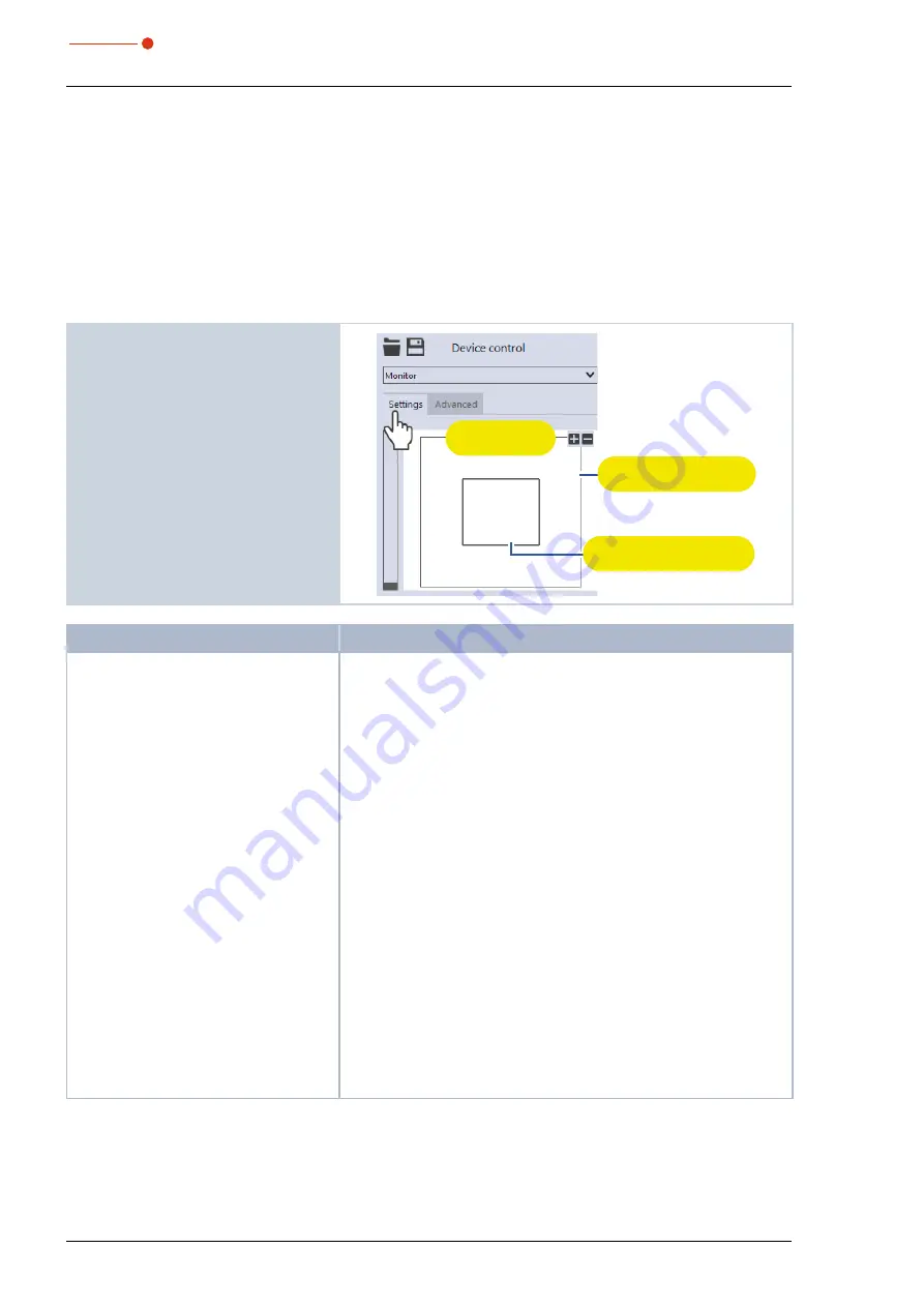
9.6.1
Configure settings
1. Click on the
Settings
tab.
2. Maintain the options according to the
explanations in in the following table..
Graphic
representation
Measurement window
(thick line)
Measurement range
(thin line)
Option
Explanation
Graphic representation
In a window in the upper area of the
Settings
tab, the measurement
plane is displayed graphically. Here you can see:
• the entire measurable area (measurement range, thin lines)
• the area to be recorded (measurement window, thick lines)
• after a measurement a false-color image of the recorded area
You can make changes in the graphic representation as follows:
X
To create a new measurement window, position the mouse pointer
anywhere within the measurement range. Drag while holding down
the left mouse button. Keep the mouse button pressed until the
measurement window meets your requirements.
The maximum size of the window depends, among other things, on
the magnification of the measuring objective).
X
To move the measurement window to another location, position the
mouse pointer inside the measurement window. Drag while holding
down the right mouse button.
X
To zoom to the center of the graphic representation, first move the
mouse pointer over the graphic representation until the plus / minus
buttons appear. Then press the buttons.
X
To zoom in on the position of the mouse pointer, position the mouse
pointer anywhere within the graphic representation. Then turn the
mouse wheel.
X
To set the zoom section to the size of the measurement window,
position the mouse pointer inside the measurement window. Then
double-click left.
X
To set the zoom section to the size of the measurement range,
position the mouse pointer outside the measurement window. Then
double-click left.
Tab. 9.5:
Options in the
Device control > Settings
tab of the
Monitor
measuring mode
Summary of Contents for MicroSpotMonitor Plus HighBrilliance
Page 2: ......
Page 3: ...3 Revision 00 EN 02 2022 MSM HB 35 0 6 IMPORTANT READ CAREFULLY BEFORE USE KEEP FOR FUTURE USE...
Page 7: ...7 Revision 00 EN 02 2022 MSM HB 35 0 6...
Page 95: ...95 Revision 00 EN 02 2022 MSM HB 35 0 6 13 Declaration of conformity...
Page 96: ...96 Revision 00 EN 02 2022 MSM HB 35 0 6...
Page 98: ...98 Revision 00 EN 02 2022 MSM HB 35 0 6 15 Dimensions 15 1 Dimensions of the MSM HB10 A...
Page 99: ...99 Revision 00 EN 02 2022 MSM HB 35 0 6 Dimensions of the MSM HB10 continued View A...
Page 100: ...100 Revision 00 EN 02 2022 MSM HB 35 0 6 15 2 Dimensions of the MSM HB10 with fibre bridge A...
Page 103: ...103 Revision 00 EN 02 2022 MSM HB 35 0 6 15 3 Dimensions of the MSM HB20 at zmax C...
Page 104: ...104 Revision 00 EN 02 2022 MSM HB 35 0 6 Dimensions of the MSM HB20 continued View C...


