background image

10  

I I I .   YO U R   S C O O T E R

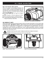
Safety Flag Bracket

An accessory bracket for installing an optional 

safety flag is mounted near each anti-tip wheel. To 

install the flag, the supplied “L” shaped hex key is 

needed. 

See figure 5.

Installation:

1.  Remove the cap from the top of the bracket.

2.  Loosen the setscrew with the supplied “L” 

shaped hex key.

3.  Insert the flag pole into the opening.

4.  Tighten the setscrew to complete installation.

Figure 5. Safety Flag Bracket

Manual Freewheel Lever

Whenever you need or want to push your scooter for short distances, you can put it in freewheel mode.

1.  Remove the key from the key switch.

2.  Push forward on the manual freewheel lever to disable the drive system and the brake system. You 

may now push your scooter.

3.  Pull back on the manual freewheel lever to reengage the drive and the brake systems and take your 

scooter out of freewheel mode.

WARNING! When your scooter is in freewheel mode, the braking system is disengaged. 


„

Disengage the drive motors only on a level surface.


„

Ensure the key is removed from the key switch.


„

Stand to the side of the scooter to engage or disengage freewheel mode. Never sit on a scooter 

to do this.


„

After you have finished pushing your scooter, always return it to the drive mode to lock the 

brakes. 

WARNING! Failure to heed the above could result in personal injury and/or damage to your scooter.

NOTE: If the scooter is placed in freewheel mode (manual freewheel lever forward) while the 

key is in the “on” position, the scooter will not run until the manual freewheel lever is pushed 

rearward and the key is turned to the “off” position, then back to the “on” position.

HEX KEY

CAP

SETSCREW

Summary of Contents for CELEBRITY DELUXE

Page 1: ...CELEBRITY DELUXE OWNER S MANUAL OPERATION COMFORT MAINTENANCE BATTERY CHARGING...

Page 2: ...this owner s manual and on the scooter to identify warnings and important information It is very important for you to read them and understand them completely WARNING Indicates a potentially hazardous...

Page 3: ...UCTION 4 II SAFETY 5 III YOUR SCOOTER 7 IV BATTERIES AND CHARGING 12 V OPERATION 17 VI COMFORT ADJUSTMENTS 19 VII DISASSEMBLY AND ASSEMBLY 22 VIII BASIC TROUBLESHOOTING 24 IX CARE AND MAINTENANCE 26 A...

Page 4: ...thorised Pride Provider Failure to follow the instructions warnings and notes in this manual and those located on your Pride product can result in personal injury or product damage and will void Pride...

Page 5: ...s It is very important for you to read and understand them completely NOTE There are more warnings identified and explained in the Consumer Safety Guide that is included with your scooter Please becom...

Page 6: ...mation sheets and booklets included in your Owner s Package Please fully read and review the information and keep it readily available for future reference Below are some precautions tips and other sa...

Page 7: ...Turn the key anticlockwise to power down turn off your scooter WARNING If the key is moved to the off position while your scooter is in motion the electronic brakes will engage and your scooter will c...

Page 8: ...rd speed and the reverse speed of your scooter up to the maximum speed you preset with the speed adjustment dial To Move Forward use either of the following Use your left thumb to push the left side o...

Page 9: ...al freewheel lever the anti tip wheels and the motor transaxle assembly are located on the rear section of your scooter See figure 4 Anti tip Wheels The anti tip wheels are an integral and importantsa...

Page 10: ...now push your scooter 3 Pull back on the manual freewheel lever to reengage the drive and the brake systems and take your scooter out of freewheel mode WARNING When your scooter is in freewheel mode t...

Page 11: ...scooter provide securement points See figures 7 and 8 These should only be used with an unoccupied scooter and secured by an approved securement system in accordance with the manufacturer s instructio...

Page 12: ...ive gases may be generated while charging the batteries Keep the scooter and battery charger away from sources of ignition such as flames or sparks and provide adequate ventilation when charging the b...

Page 13: ...heel lever is in the drive position 4 Make sure that the charger s on off switch is in the OFF position See figure 10 5 Plug the 3 pin charger power lead into the off board charger port See figure 11...

Page 14: ...scooter will be ready each morning We recommend that you charge your scooter s batteries for 8 to 14 hours after daily use If you use your scooter once a week or less charge its batteries at least onc...

Page 15: ...ttery posts terminals and related accessories contain lead and lead compounds Wash hands after handling To change the batteries in your scooter 1 Remove the seat and rear shroud See VIII Disassembly a...

Page 16: ...your scooter s new batteries for maximum efficiency and service life 1 Fully recharge any new battery prior to its initial use This charging cycle brings the battery up to about 88 of its peak perform...

Page 17: ...y in place See VII Comfort Adjustments Is the key fully inserted into the key switch and turned clockwise to the on position Does the scooter s horn work properly Is your proposed path clear of people...

Page 18: ...cooter 6 You can leave the seat facing to the side to facilitate boarding your scooter next time POWER DOWN TIMER FEATURE Your scooter is equipped with an energy saving automatic power down timer feat...

Page 19: ...tiller console can be adjusted to different angles To change the console angle 1 Loosen the adjustment dial turn anticlockwise and move the tiller console up or down to a comfortable riding position...

Page 20: ...djustment nut and remove it from the bolt Remove the bolt 3 Loosen the clamp action bolt 4 Raise or lower the upper seat post to the desired seat height 5 While holding the upper seat post at that hei...

Page 21: ...he forward direction 6 Release the throttle control lever when you have attained your desired height 7 To lower the power seat operate your throttle control lever in the reverse direction 8 Ensure tha...

Page 22: ...for assistance when necessary while disassembling or assembling your scooter Figure 21 Scooter Components FRONT SECTION SEAT REAR SECTION REAR SHROUD BATTERIES BASKET Figure 23 Tiller Lock Knob Unlock...

Page 23: ...Position the front and rear sections of your scooter as shown in figure 26 2 Use the frame release lever to lift the front section as you align the frame hooks of the front section with the lower fram...

Page 24: ...on as possible 2 Battery charge is too low Charge batteries 3 The scooter s battery voltage is too high to operate the scooter or the charger is still connected to the offboard charger port Unplug cha...

Page 25: ...ansaxle assembly is cut Push rearward on the manual freewheel lever turn the scooter off and then turn the scooter on to return to normal scooter operation What if the main circuit breaker repeatedly...

Page 26: ...When changing a tyre remove only the centre lug nut then remove the tyre If any further disassembly is required deflate the tyre completely or it may explode possibly resulting in personal injury EXTE...

Page 27: ...ith a pH of 10 5 or higher may damage the vinyl surface integrity over an extended period of time Disinfecting Wipes Clorox Green Works PDI Sani Cloth HB Wipes Lysol Oxivir Virox and CaviWipes For Tir...

Page 28: ...ay wish to place several boards under the frame of your scooter to raise it off of the ground This takes the weight off the tyres and reduces the possibility of flat spots developing on the areas of t...

Page 29: ...eel Turning Radius 4 Wheel Turning Radius 61 cm 3 Wheel 116 84 cm 4 Wheel 118 75 cm 149 86 cm 105 41 cm 43 18 cm 53 34 cm 8 26 cm 50 cm 16 45 72 cm 45 72 cm Scooter Dimensions Front Tyre Dimensions Re...

Page 30: ...Standard Seating Type CRS Deluxe high back with headrest Weight 20 41 kg Material Vinyl Dimensions 45 72 cm width 45 72 cm depth 50 cm height plus adjustable headrest Drive System Rear wheel drive se...

Page 31: ......

Page 32: ...applicable Please fill out the following information for quick reference Provider Address Telephone Purchase Date Pride Mobility Products Australia Pty Ltd 20 24 Apollo Drive Hallam Victoria 3803 www...

Reviews: