background image

February 19, 2021

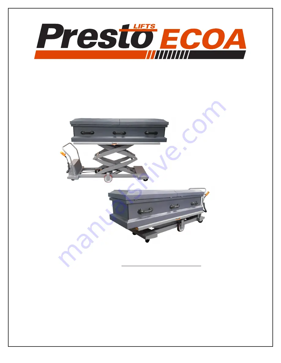
XBP68-05 Owner’s Manual

Presto Lifts Inc. 

50 Commerce Way, Norton, MA 02766 

Phone: 800.343.9322  

Fax: 888.788.6496 

www.PrestoLifts.com 

Email: [email protected]

Model:
Serial Number:

__________________________

Date placed in 

service:

__________________________

Portable DC Powered Mortuary Lift

Summary of Contents for XBP68-05

Page 1: ...s Inc 50 Commerce Way Norton MA 02766 Phone 800 343 9322 Fax 888 788 6496 www PrestoLifts com Email service prestolifts com Model Serial Number __________________________ Date placed in service __________________________ Portable DC Powered Mortuary Lift ...

Page 2: ...ing the Floor Lock 13 6 3 Raising and Lowering 14 7 Maintenance Repair 15 7 1 Securing the Lift for Maintenance 16 7 1 1 Lifts Equipped Standard or Ball Transfer Platforms 16 7 1 2 Lifts Roller Transfer Platforms 17 7 2 Periodic Maintenance 18 7 2 1 Weekly Maintenance 18 7 2 2 Monthly Maintenance 18 8 Troubleshooting 19 9 Electrical 20 9 1 Wiring Schematic 20 9 2 Electrical Arrangement 21 9 3 Batt...

Page 3: ...3 Presto Lifts XBP68 05 Manual Cancer and Reproductive Harm www P65Warnings ca gov WARNING This label part 10095524 is required by California Law For more information visit www P65Warnings ca gov ...

Page 4: ...recautions shall be taken as applicable 1 Remove the load from the platform 2 Lower platform to the full down position 3 Relieve system pressure from all circuits before loosening or removing any components 4 All controls in the off position and all operating features secured from inadvertent motion by brakes blocks or other means 5 Disconnect power and follow established owner user lockout tag ou...

Page 5: ...ing the operation of the machine 3 Factors affecting stability 4 The purpose of placards and decals 5 Workplace inspection 6 Safety rules and regulations 7 Authorization to operate 8 Operator warnings and instructions 9 Actual operation of the machine Under the direction of a qualified person the trainee shall operate the machine for a sufficient period of time to demonstrate proficiency in actual...

Page 6: ...e safety standards established for the workplace 6 Reporting problems or malfunctions The operator shall immediately report to a supervisor any problem s or malfunction s that become evident during operation The operator shall ensure all problems and malfunctions that affect the safety of operations are repaired prior to continued use 7 Capacity limitation Rated capacity shall not be exceeded when...

Page 7: ...afety red exclamation mark safety red background B For use with WARNING signal word safety black triangle safety orange exclamation mark C For use with CAUTION signal word safety black triangle safety yellow exclamation mark D For use with DANGER WARNING or CAUTION signal words D is a safety yellow triangle with a safety black border and safety black exclamation mark 2 2 Signal Words DANGER Indica...

Page 8: ...fer Platform Platform Length 74 Platform Width 30 Standard Platform 24 Roller Ball Transfer Platform Lowered Height 14 3 8 Standard Platform 16 3 4 Roller Ball Transfer Platform Raised Height 82 3 8 Standard Platform 84 3 4 Roller Ball Transfer Platform Vertical Travel 68 Primary Control Voltage 12 VDC Maximum Load Capacity 500 lb Machine Weight Approximately 715 lb ...

Page 9: ...8 TRAVEL VERTICAL LOWERED HEIGHT 16 3 4 84 3 4 RAISED HEIGHT 16 1 4 20 7 8 35 5 8 86 1 8 24 PLATFORM 24 3 4 BASE FRAME SIDE LOAD ROLLER TOP HEIGHT 16 3 4 LOWERED TRAVEL VERTICAL 68 84 3 4 RAISED HEIGHT PLATFORM 74 PLATFORM 24 86 1 8 OVERALL 24 3 4 BASE FRAME 35 5 8 16 1 4 20 7 8 STANDARD PLATFORM VERTICAL 68 TRAVEL HEIGHT 14 3 8 LOWERED 82 3 8 RAISED HEIGHT 16 1 4 20 7 8 35 5 8 86 1 4 74 PLATFORM ...

Page 10: ...2 LD 1 62x7 00 PRESTO ALPHA C180N 3 2 LD DCL 1 00X6 00 A DANGER TO AVOID BODIL 10089458 2 4 BK LD DCL 1 25X2 75 CAPACITY 500 LBS 2998433 1 4 LD DCL 1 00X8 50 TO AVOID BODILY INJURY 10089457 3 4 APPLY TO BOTH SIDES OF PLATFORM AS SHOWN 1 2 2 APPLY TO BOTH ENDS OF PLATFORM AS SHOWN 7 9 6 5 10 4 Labeling This machine has labeling to indicate potential hazards this machine may pose when operating and ...

Page 11: ...hine for damage Verify all components were received If damage is found or components are missing do not continue the setup procedure contact Customer Service 2 Remove the battery cover by lifting up on the cover Connect the cables to the battery terminals Connect the positive lead of the battery charger to the positive terminal on the battery Ensure the negative lead of the battery charger is conn...

Page 12: ...begin to raise 6 Raise the lift approximately one foot then release the button The motor should turn off and the lift should come to a stop and hold its position 7 Press and hold the up button and raise the lift to the fully raised position Release the button when the lift reaches the end of travel 8 Do not continue to power the lift after the lift reaches the end of travel or the lift may be dama...

Page 13: ...or must be in view of the machine at all times The lift must only be used indoors on smooth level surfaces Machine should be in the fully lowered position when not in use The platform must be in the fully lowered position before moving the lift Engage the floor lock before loading unloading and raising lowering the platform to prevent the lift from shifting The floor lock is not a braking device I...

Page 14: ...vel To lower the platform press and hold the DOWN button on the controls Release the button when the platform is at the desired height Release the button once the lift reaches the end of travel Do not continue to power the lift once the lift reaches the end of travel Plug the battery charger in when the lift is not in use The battery charger supplied with this lift will not over charge the battery...

Page 15: ...pply before performing any maintenance or repair Do not adjust the hydraulic pressure relief valve This valve is pre set and adjustment may cause the machine to fail Before performing maintenance or repair to the hydraulic components relieve pressure in the hydraulic system Pressurized fluids can penetrate skin and cause severe injury Do not use hands or other body parts to detect hydraulic leaks ...

Page 16: ...Ball Transfer Platforms To properly secure the lift for maintenance 1 Lower the lift to the fully lowered position 2 Engage the floor lock to prevent unintended movement of the lift during maintenance 3 Disconnect the power source to prevent unintended operation of the lift during maintenance 4 Lift up on the roller end the end closest to the push bar of the platform and hinge it up high enough to...

Page 17: ...the internal components of the lift the platform rollers can be removed To remove the platform rollers press in on the hexagonal spring loaded axles and lift the roller out of the platform frame Take care not to damage the roller when removing it and store it in a safe location during maintenance END LOAD ROLLER TRANSFER PLATFORM SPRING LOADED HEX AXLE BOTH SIDES EACH ROLLER SPRING LOADED HEX AXLE...

Page 18: ...ly Maintenance Perform Weekly Maintenance Apply a dry PTFE lubricant to non greased pivot points or rollers Inspect the appearance or the hydraulic fluid See section 10 1 Hydraulic Fluid Inspect the hydraulic cylinder all hydraulic hoses and fittings Repair or replace as necessary Inspect all electrical wiring and connections Repair or replace as necessary Inspect limit switches if applicable Repa...

Page 19: ...ulty Verify solenoids are functioning correctly Replace as necessary Low hydraulic fluid level Verify hydraulic fluid level Add fluid as necessary See section 10 1 Hydraulic Fluid Hydraulic fluid leak Inspect all hoses and fittings for leaks Repair replace components as necessary Thermal relief valve is open Allow the hpu to cool then attempt to raise the lift again Contact Customer Service if lif...

Page 20: ...ctrical Primary Voltage 12 VDC Control Voltage 12 VDC Battery AGM Sealed Lead Acid Battery Nominal voltage 12 VDC Nominal capacity 20 hour rate 55 Amp Hours Group Size 24 Motor 1 3 HP 3450 RPM 12 VDC intermittent duty 9 1 Wiring Schematic ...

Page 21: ...21 Presto Lifts XBP68 05 Manual 9 2 Electrical Arrangement BATTERY CHARGER POSITIVE TERMINAL NEGATIVE TERMINAL UP DOWN SOLENOIDS MOTOR ...

Page 22: ... on the battery This charger must not be exposed to dirty or wet conditions Do not operate the lift while the charger is plugged in Charger Description Automatic 3 Stage On Board industrial battery charger AC Input 115 V 1 Ph 60 Hz 1 6 Amps DC Output 12 VDC 6 Amps Led Indicators On Off Condition Red Green Charger is in the Soft Start or Bulk Stage and the battery is being charged Red Green None Ch...

Page 23: ...onoco AW32 Use only the same or other compatible fluid when adding or replacing fluid The hydraulic fluid reservoir is to be full approximately 3 4 below the fill plug only when the lift is in the fully lowered position The hydraulic fluid should be transparent with no burnt or rancid smell 10 2 Hydraulic Schematic ...

Page 24: ...24 Presto Lifts XBP68 05 Manual 10 3 Hydraulic Arrangement HPU MOTOR HPU PUMP HYDRAULIC FLUID RESERVOIR FILL PORT BREATHER FIXED DOWN SPEED FLOW CONTROL DOUBLE ACTING CYLINDER ...

Page 25: ...n at Presto Lifts discretion This is buyer s sole remedy under any such warranty sale agreement or contract Presto Lifts will not be liable for consequential incidental exemplary or punitive damages of any kind resulting from a breach of any warranty that it has provided or for breach of any term of any sale agreement or contract Any warranty may be altered only in writing by Presto Lifts All comm...

Reviews: